* GadgetBuilder.com *
Last Modified:
Click to enlarge
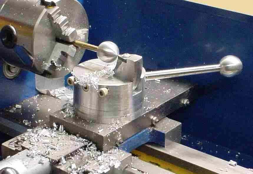
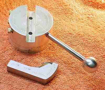
This ball turning attachment for the minilathe is based on Steve Bedair's design
for his 9X20. Here's another view. It uses a TNMG insert which is necessarily angled downward 5 degrees (see tangential tool holder below).
This design has a large bearing surface for the rotor plus minimal extension of the cutter from its holder to minimize the chance of chatter.
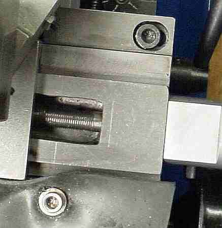
In use the attachment replaces the compound slide and is secured to the cross slide via two socket head screws accessed through the toolholder slot as shown in this picture. The cutter must be on the centerline so once I found this position of the cross slide I scribed a witness mark on the carriage to simplify subsequent use. The steel for the tool holder was part of a trailer hitch in its prior life and the ball on the handle was made using the ball fixture, of course.
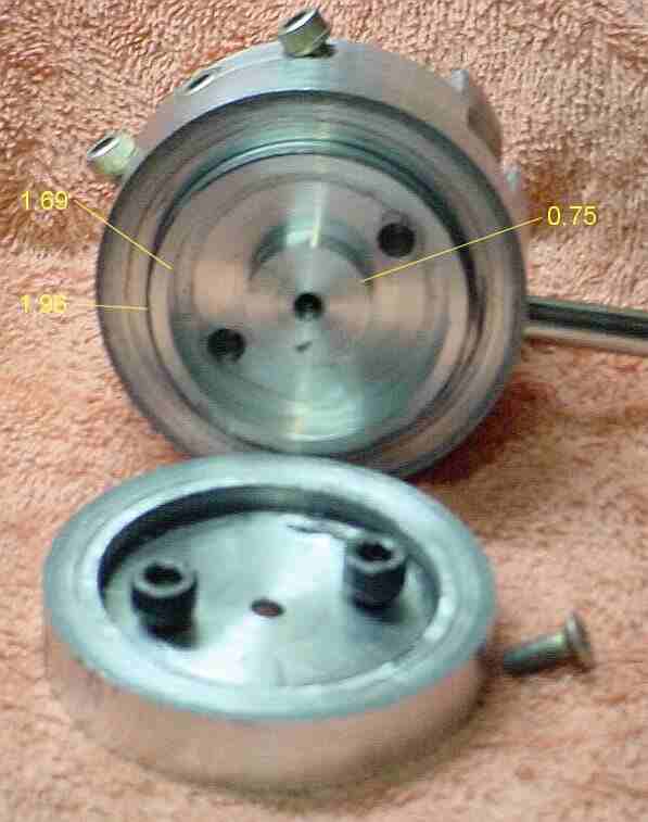
The internals differ from Steve's because the bolts which secure the base to the cross slide are under the rotor. This requires some additional work to provide clearance for the heads of the securing 11mm long M6.1 socket head bolts; in duplicating this design you may have to adjust the internal dimensions slightly if your bolt heads are larger than 0.394 dia.
The material used for the rotor is 2.75 dia scrapyard aluminum round, turned down to remove most of the corrosion (some still shows, as seen in the pictures). The shoulder is 0.165 high so that it easily clears the base which is bored 0.180 deep. The inside between the shoulder and the center is deeper to provide clearance for the bolt heads, 0.265 for the hex holts I found at the hardware store. I chamfered outside corners slightly as needed so I didn't have to get the interior corners to zero radius. The rotor was d/t 10-32 for the flathead screw which holds the rotor to the base when the attachment is off the lathe; don't tap full depth, tap so the thread binds before the rotor/base binds. The rotor was completed first and then the base was bored carefully so that it fit snugly onto the rotor. The bearing surface is a combination of the horizontal and vertical surfaces where the rotor and base meet -- grease is used on both surfaces to provide a smooth feel and good damping to avoid chatter. A ball bearing could have been used but would add complexity and provide less damping.
The overall height of the rotor + base is 1.48 inches. The slot in the rotor was milled on the lathe while holding the rotor in the toolpost mounted vise (as described on my home page). The access holes are in the slot so that the tool holder prevents swarf from entering -- this does require that the tool holder be removed in order to remove the attachment so put the holes elsewhere if this will be a problem.
The base is 1/2" thick aluminum whose outside diameter is turned to match the rotor. The center is bored out to a depth of 0.180 inches. The holes for the bolts which secure the base to the cross slide pivot are 1.25 inches apart. The center hole is drilled to clear the 10-32 flat head screw which holds the rotor to the base and counterbored so this screw head clears the cross slide rotor's center land.
The tool holder is 1/2 inch thick steel sawn and filed to shape. The seat for the TNMG carbide insert was milled, again using the toolpost mounted vise. This seat was adjusted to put the carbide insert's tip at exactly center height. The tool tip is 0.717 above the base so ball diameter is limited to 1.43" -- the base could be made lower and the toolholder higher to allow a larger diameter. Attachments for the 7x12 are relatively small so I've never made a ball larger than 1.25" and consequently, this setup has worked out for me. A TPEG insert might have been a better choice than TNMG because it wouldn't need the -5 degree angle so it would be simpler to make...
Increasing cross slide travel required removing material from the cross slide (done after the ball cutter pictures were taken) which exposes the lead screw when the cross slide is advanced to put the ball cutter on the center line. I use a magnetic advertising card (refrigerator magnet) to cover the opening. The ball cutter needs to be exactly on the center line so I added a witness mark on the cross slide to make it easy to position it.
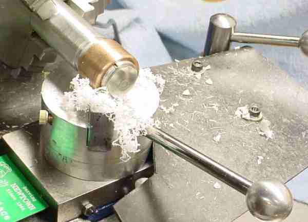
It's interesting to watch this tool work -- it quickly produces an amazing amount of swarf. It is useful for
things other than making ball handles: anything that needs a modest radius is fair game, e.g. see my note on
Coddington magnifiers. In fact, I have made many more Lucite lenses than ball handles,
e.g. the optical center punch and the drill sharpener alignment fixture.

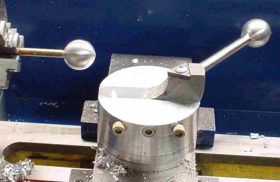
I helped a friend make a ball cutter and suggested we make the tool holder a tangential design rather than carbide. The base (see above) is the same in any case so if it didn't work out we could recover by making another tool holder. The tangential design works well and was fairly easy to build. Some 1/8" round HSS was left over from graver experiments so a hole was drilled and reamed on the center line of the holder 1.125" from one end and inclined 12 degrees as in a regular tangential holder. This hole was opened on the bottom 1/2" deep for an 8-32 set screw to adjust tool height. An intersecting hole was drilled and tapped 6-32 for a knurled brass locking screw. The 1/8" HSS was cut to length and then sharpened in the regular tangential tool's sharpening jig. I whittled the area to the sides of the tool away with a ball end mill then smoothed the whittle marks with a die grinder.
 Here the tangential ball cutter is making its 0.9" handle (I borrowed the handle from my original temporarily) -- as usual with ball cutters there is lots of swarf in very little time. Initially I had the tool way too low and there was massive chatter; I found the way to set the tool height is to put a small drill in the tailstock, turn the tangential toward this drill and use this to judge height. It takes some trial and error to set height because the tool holder must be removed to access the height adjustment. However, once it's set it probably won't need adjusting again until the tool gets dull. If you look carefully at the picture you can see a large pip on the end of the ball caused by low tool height and stock longer than necessary (it cleaned up nicely once I got tool height right).
The knurled handle on the brass locking screw can contact the right end of the work initially when the raw material is over 3/4" and perhaps a little longer than necessary. There are a couple ways to handle this: easiest is to move the carriage to the right slightly and rough the right end of the work then move the carriage back to the center of the work area and lock it in place. Alternatively, replace the knob with a set screw - height seldom needs adjustment so it shouldn't be a hardship.
Overall, I like the tangential version and were I starting over I'd likely use this in preference to my original approach.
A reference to the Tippee Top got me
thinking about making one for my grandson. I made a 1/2" plastic version initially because it was easy to make
by trepanning; unfortunately, it didn't invert. So, I made a larger version from aluminum.
 This one inverts if started
with sufficient rotation speed - not so easy to do because often it gets launched with some sideways velocity and
zips off of the desired surface. If started properly the stem precesses downward in 2-3 seconds, rattles on the
table for a fraction of a second, and hops up onto its stem and spins inverted. Not an intuitive result - it took
physicists years to explain its operation.
This one inverts if started
with sufficient rotation speed - not so easy to do because often it gets launched with some sideways velocity and
zips off of the desired surface. If started properly the stem precesses downward in 2-3 seconds, rattles on the
table for a fraction of a second, and hops up onto its stem and spins inverted. Not an intuitive result - it took
physicists years to explain its operation.
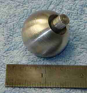
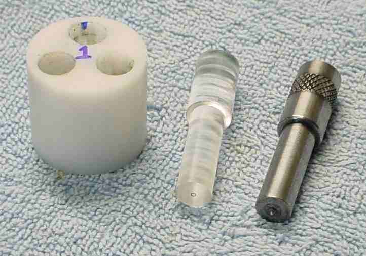
It's a nice project for the ball cutter but the top's dimensions affect its operation. This one works well; other dimensions may work better - or not at all. The diameter of the ball is 1.24". The 1.25" round is cut to 1.3" length and the 0.77" deep hole is drilled to 1/2" then bored to 0.58"; the bottom of the hole was flattened with a 1/2" end mill (optional). The hole was drilled through with a #3 and tapped 1/4-28. The end of a 0.312 round was turned down to 0.25" for about 0.6" and threaded 1/4-28. This shaft is threaded into the hole in the stock to hold it while turning the ball. The part of the shaft that extends below the ball is rounded in the process of making the ball, of course. The shaft will be difficult to impossible to remove after making the ball, depending on how hot the ball gets while cutting. Part the shaft so the stem protrudes about 0.31".
As a check on construction: the center of gravity must be below the center of the ball. If the stem is held horizontal and released the stem should oscillate from side to side with a period of about 1 second and come to rest with the stem near vertical. Theoretically you can hold the ball with the stem horizontal and flick the stem to launch it - this might work with a plastic top but the mass of the aluminum version makes it difficult.
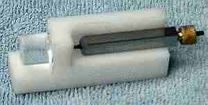
The top needs a "launcher" to get it up to speed without imparting lateral velocity that causes it to go off the table on most starts. It isn't suitable for children without this; I haven't decided whether I can make a launcher easily or not... An electric eraser of the type draftsmen used in days of yore might do it.
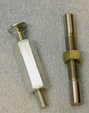
The toy on the left is called a "Sneaky Puzzle" (near the bottom of that page). It's sneakier than I realized: once assembled it doesn't come apart again so be sure you follow the advice to debur carefully prior to putting the coupling nut on. Or slot the end so a screwdriver will work.
The toy on the right is the captive nut described at the Frets site. I'd been threading 24 TPI and found a 3/8-24 nut in my junk box so a bit of line printer rod and a few minutes work did the trick. Rather than using threaded rod as Frank Ford did, I turned a 1/4" spigot and threaded it 24 TPI (Surprise!) since I had a 1/4-24 tap. I didn't use Locktite, just put a piece of paper around the end of the toy to avoid marring it, gripped it in the tailstock chuck, and turned the 3 jaw by hand to tighten it up firmly. The joint is definitely invisible, even with a magnifying glass. A loose fit makes it easy to spin the nut back and forth - a natural action when you pick this toy up.
If you have a comment on my site or its contents, click here.