* GadgetBuilder.com *
Last Modified:
The compound shaft on my minilathe had a very rough feel and was hard to turn. In addition, there was about 7.5 thou backlash in the setting when reversing directions - not a big problem, but less would be better.
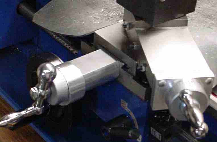
After the effort expended completing the cross slide mod I was looking for an easier way to add a ball bearing on the compound shaft. The approach selected was to turn the end of the compound shaft down in the area under the dial; this allowed addition of a clamp to hold the dial. The area under the spacer (for a distance corresponding to the width of the [future] ball bearing was left alone and the shaft between that point and the knob was turned to match the diameter under the knob. A collar (drill size "O") was made to fit over the shaft and hold the dial using the original spring - with the collar installed the shaft looks as it did initially. This is the resulting test setup prior to selecting the bearing size. When assembled this looks original but the length of the collar can be adjusted to reduce the backlash in the compound settings by reducing the length of the collar until there is minimal visible movement of the dial between forward and reverse rotation. This allowed reducing the backlash to 4 thou in my machine by using a file to tune the length of the collar. As a fringe benefit, once the collar and spring are installed into the dial they need not be removed when diassembling thereafter - the spring always attempted to make its getaway prior to this change.
I decided to use the smaller 608-2RS bearing instead of the 6001-2RS used in the cross slide. This choice was made for simplicity - the larger bearing's inner race would have rubbed on the compound slide, requiring measures to avoid this. The smaller bearing's outer race contacts the slide (an alternate way of retaining the bearing) but the inner race clears it nicely.
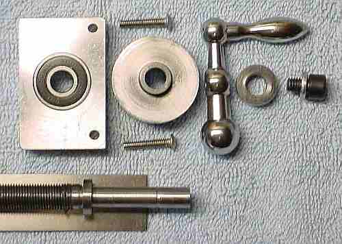
An aluminum spacer was made to hold the bearing using a press fit; the bearing was pressed into the spacer by squeezing in a vise. The shaft was further modified by turning it down to fit the bearing such that the inner race contacts the original shoulder on the shaft. A clamp was made to replace the collar (the clamp is about 50 thou longer than the collar, otherwise they're identical); the inner bearing race is held between the original shoulder and the inner end of this clamp. The spacer was drilled for 6-32 button head retaining screws and the end of the compound slide was drilled and tapped to accept these screws. Here is the resulting parts lineup with the clamp and spring in the dial. The dial side of the spacer was turned to leave a raised land matching the dial. Not shown are two holes on the dial side of the spacer for use in bearing extraction if that is ever needed; these holes are in line with the outer race and are tapped 6-32.
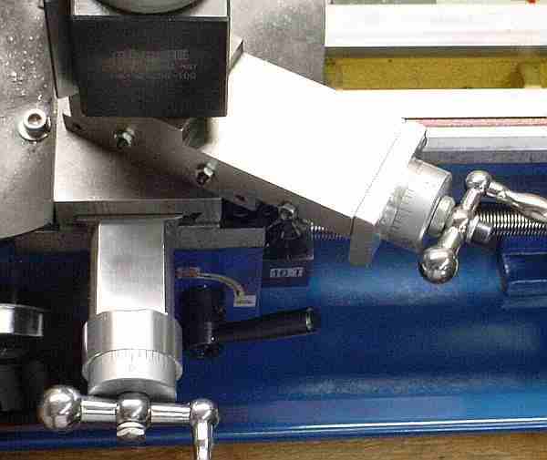
As shown here and here the spacer is rectangular and as wide as the compound to acommodate the new retaining screws; the placement of the original screws conflicted with the new bearing. It would be more attractive if the lower half of the spacer were removed up to the turned section but I couldn't think of an easy but tidy way to do this.
Although the setup looks similar to the original, the concept is quite different, more like the cross slide - the dial no longer takes the thrust through to the knob. Instead, the thrust is passed via the clamp to the washer and then to the knob. Since the bearing is gripped tightly by the force generated by the screw through the handle, the only movement is due to axial play in the ball bearing, about 1 mil - you can see this when the gap between the spacer and the dial opens or closes as direction changes. This happened with the original design too, but then force was transmitted via the dial and the gap was larger although this varied between machines. A ball bearing with pre-load should eliminate the remaining 1 mil from this source but would probably cost more than 44 cents.... There is a little humor to this: I started out trying to adapt the compound's design concept to the cross slide and wound up adapting the cross slide concept to the compound.
This mod is relatively easy (compared to the cross slide), inexpensive and works well. The shaft now turns smoothly and easily but there is about 4 thou of backlash remaining, mostly due to the fit of the leadscrew into its thread - mods to remove this are available too. If you decide to add this bearing then consider adding a dial lock at the same time, not much extra effort when they are done simultaneously.
This bearing mod isn't instantly reversible (unlike the cross slide mod) because the lead screw shaft is modified; to go back to the original setup one must add a collar (along with the clamp) to make the lead screw look like it did originally, then put the old spacer back.
If you're unsure whether a BB is worth the effort it is possible to do this mod incrementally, stopping when you're happy with the result. Begin with the test setup - you need only a small piece of steel to make the clamp and you can verify the fit by trying it on the knob section of the shaft; it takes only a short time to make this simple piece and verify that the spring fits the groove and the clamp fits into the dial properly. Make it perhaps 15 thou longer than required to allow tuning the length later. Once you make the clamp and are happy with it you need only turn down the first section of the compound shaft and install the new part. However, allow some time to adjust the length of this clamp with a file (re-chuck if it is more than a little too long) to reduce the backlash in the compound -- if backlash reduction is your only goal, you're done.
If you would like to improve smoothness then proceed to the next step: comparing the test setup to the final setup you can see the material that must be removed from the shaft to accommodate the ball bearing. If, instead, a piece of bronze or brass is carefully fitted to replace the metal removed from the shaft then you have a nice plain bearing (which you can custom fit for smooth running) and the ability to tune the length to remove backlash with no need for a new spacer. (This plain bearing needs a thin rim on the end towards the dial so the spacer is caught between this rim and the shoulder on the shaft. The bearing is clamped to and turns with the shaft.) Given that the compound isn't used too much this would be a good compromise with smooth operation and minimal backlash; you can make the spacer and add a ball bearing later if desired -- this is more effort than the first two increments, plus you have to locate a ball bearing and material for the spacer.