
Click to Enlarge
* GadgetBuilder.com * © 2014 by John Moran
Last Modified:
Click to Enlarge
 Cut knurlers are less common than pressure knurlers in home shops, where each type has its advantages. My AXA toolpost came with a bump knurler but I quickly found this wasn't suited to most of the knurling tasks in my shop so I made a clamp knurler per Martin Cleeve's design. This works well for modest size items, up to somewhat over an inch in diameter. I resorted to the bump knurler for larger items but was seldom satisfied with the result. A friend demonstrated a Dorian cut knurler which works well over a 5:1 range, e.g. 5/16"- 1.5"; three tools are needed to cover the complete diameter range... and they're very expensive.
I found Tom Partington's design for a cut knurler and decided to build one (with some changes) as an experiment. Cut knurlers produce a diamond pattern using straight knurl wheels and some can produce straight knurling using diagonal knurl wheels; I assume this design is limited to diamond knurling because the knurl angle is adjustable. Adjusting the knurl angle accommodates a fairly large range of work diameters. The forces involved with a cut knurler are much lower than those with a pressure knurler so I used mild steel I had on hand. The square steel scrap I used for the body (2x1.5x1) wasn't large enough to include dovetails for the AXA toolpost so my experimental knurler mounts in a regular tool holder. A vendor at Cabin Fever had used knurl wheels for $1 each so I picked through them to find a couple pair.
There is an even simpler build concept for a cut knurler using a single knurl; this requires two passes, of course, with the wheel angle changed between passes. I haven't tried it so can't comment on how well it works in practice.
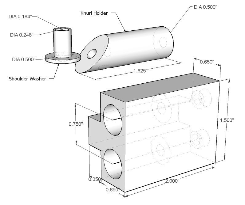 There are only 5 parts to make, as seen in the sketch at right: the main block, two knurl holders and two shoulder washers. Commercial units use hardened parts for the washers and shafts - I doubt this is necessary for the amount of knurling I do but YMMV. The 0.500" holes in the main block are 1" deep, 0.750" apart(for use with 0.750 dia. knurls), and reamed to size. This took some doing - drilling to near full size, then a resharpened 1/2" end mill (0.487) to flatten the bottom of the hole, and then a 1/2" reamer to finish to size. (The depths on my two holes differed by about 10 thou so I adjusted the lengths of the knurl holders as noted below.) A clearance hole for 10-32 continued from the center of this hole and the outer end was counter sunk to handle the head of the 10-32x1.5 socket head screw. The block was cut away with the shaper to leave a tongue to allow mounting in the tool holder.
I used a 3" length of 1/2" line printer shaft for the knurl holders - this is accurately ground so it fit the reamed holes nicely. The center of the 3" length was marked with a sharpie, the material clamped at 45° and cut with a slitting saw at the center line; this ensures the same angle on both holders.
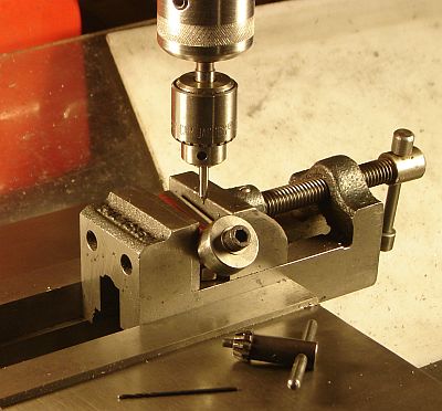
 The end of the part in the vise was drilled perpendicular at the center for a 10-32 tap, right through and out the other side. The other holder was carefully placed in the vise with the 45° face horizontal and drilled similarly. I used an insert vise to hold these and moved it to my tapping fixture, ensuring proper tap alignment (getting the second knurl holder aligned for drilling took some fussing). The knurl holders were then end drilled as deep as possible without hitting the 45° hole and tapped 10-32.
 The shoulder washers were made from the same 1/2" material - if you expect to do a lot of knurling then use drill rod and harden. The end was turned down to 0.248 for a nice fit in the knurl; length of this section was trimmed with the knurl in place to leave about 5 thou beyond the knurl. The center was drilled for a close fit on a 10-32 screw. It was parted off with more than 0.050 thickness for the washer; it was then held (gently) in the chuck by the 0.250 section and faced so the washer thickness was 50 thou.
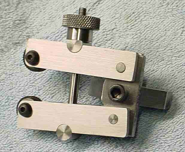
Assemble the knurls to the holders using 10-32x3/4" socket head screws and thin washers under the head; ensure the knurls turn freely. Put the holders into the main block and swivel the knurl holders so the knurls are parallel and mesh (this is why it's convenient for the distance between knurl holders to equal the knurl diameter). If the knurls are not at exactly the same height, try swapping holders between holes for the best match, then trim the holder for the higher knurl to improve the match. Add a witness mark so it's easy to put back correctly. Use a Sharpie to mark where the holder exits the main block so the hole for the alignment wires will be accessible (see next step).
 Make an alignment disk 0.6 to 0.75 diameter and about 3/8" thick with a close fit hole for 10-32 in the center. Secure this to one of the knurl holders and use it to set the holder straight in the vise by touching the disk to both vise jaws and with a lathe bit under the knurl holder to keep it horizontal, per the picture at right. Drill a hole to accept the angle alignment wire; I used 0.047 piano wire but most any stiff wire should do if you have a drill to match.
 My intuition is the knurls should be angled equally but in opposite directions. To do this simply I made a guide similar to a protractor with a 1/4" wide tail that fits snugly between the knurl holders. The knurl angle is adjusted to accommodate the work diameter. To do this loosen the bolt in the end of the knurl holder and rotate the holder so the knurl wheel is tangent to the work on the leftmost 1/3 of the knurl and re-tighten the bolt. Insert the 0.047 piano wire in the hole in that knurl holder and note the angle as shown by the wire's position relative to the marks on the guide. Move the wire to the hole in the other holder, loosen its bolt, and adjust that holder to the equal but opposite angle and re-tighten the bolt. Angles need to be close but a couple degrees difference doesn't seem to affect the resulting knurl noticeably. The height setting, however, is more critical. Move the knurls so they're adjacent to the work and advance the cross slide until one of the knurls touches the work - spin the knurl to judge contact. Adjust the tool holder's height and cross slide position until both knurls touch with similar friction on the work. Verify that the tool height doesn't change as the tool holder is locked to the tool post - make slight adjustments as needed.
I tried mounting this knurler in a regular QCTP holder on the front of the toolpost as shown in the PM thread and found the cross slide had to be retracted considerably from the position used to turn the work to the diameter being knurled. Mounting the knurler on the side of the tool post reduces this considerably, depending on where it is positioned in the holder's slot. As a fringe benefit, the depression between the 1/2" holders isn't needed, simplifying construction. The Zeus commercial knurlers rotate the knurl holders but the knurl holders are oriented with the axis parallel to the work axis -- again, several expensive tools are needed to cover the complete range of work diameters. My experimental unit works well but if I make another I will likely use a larger piece of steel for the body so a dovetail can be included to reduce stick-out from the QCTP and orient the knurl holders parallel to the work (i.e. copy the Zeus arrangement).
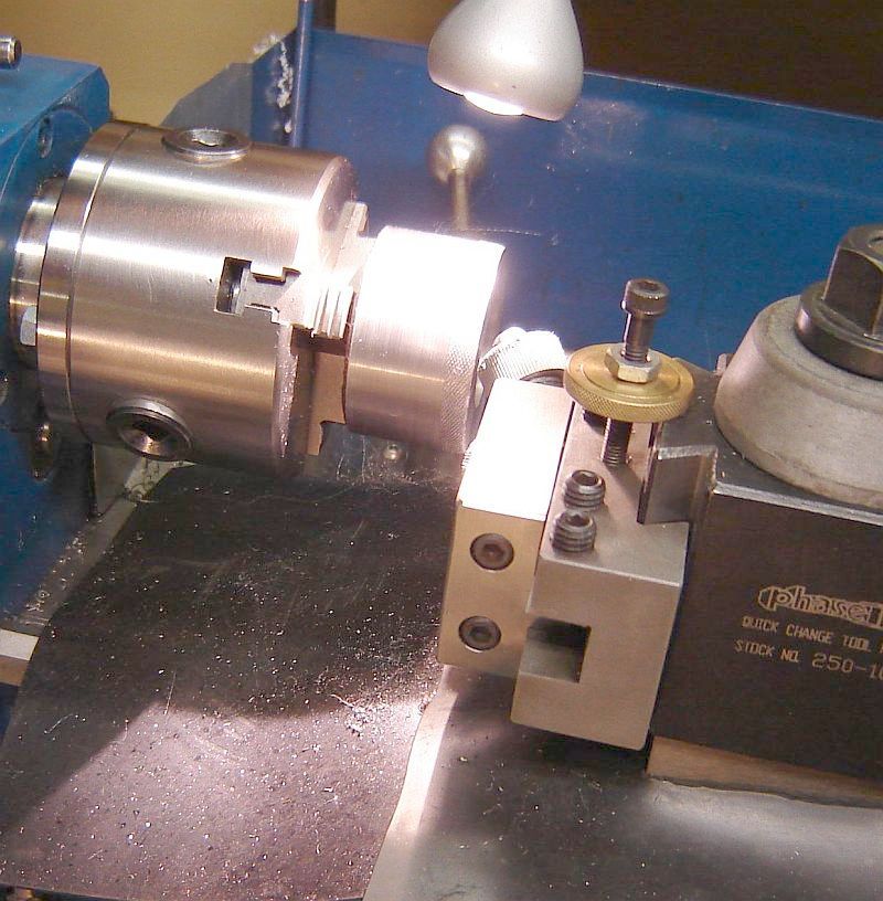 This picture shows the knurler retracted and moved right for visibility of the knurl just cut. Note the sawdust type chips on the face of the top knurl and on the way cover. If you look carefully you'll see damage on the right edge of the knurled area from an attempt to knurl this 2" diameter with the setting used previously for 0.3" diameter - the knurl scraped and sort of chamfered the corner rather than knurling. Adjusting the knurl angle allowed making the knurl shown. This knurl is acceptable quality so the knurler has at least a 10:1 diameter range; more testing is needed to determine the maximum diameter it is capable of knurling. I successfully knurled a relatively thin tube, one that would be crushed by pressure knurling.
Commercial cut knurlers warn of heat buildup and suggest flood coolant to control temperature and remove chips. So far I've run at about 100RPM with a light coating of oil on the work. Chips haven't damaged the knurls that I've noticed and there has been no heat buildup, i.e. home shop conditions may be much more benign than commercial usage. Knurling does slow the speed slightly so there is some load but the process seems much easier on the lathe than pressure knurling.
I've done a little experimenting with my cut knurler and found some details differ from what I expected based on reading about it. E.g. the diameter grows slightly (about 8-10 thou with the knurls I'm using) where I expected no diameter increase. Could be due to burrs from the knurl and this is about 1/3 of the diameter increase with these knurls in a pressure knurler. Also, the cut knurler produces a sort of rolled burr at the starting edge of the knurled area, enough so it needs to be chamfered or filed, just like a pressure knurl. I've also found that if a knurl isn't deep enough then the cut knurler will re-sync and cut it deeper - at least it has the 3 times I tried it(brass and steel). Knurling plastic (HDPE, Nylon) works better than with the pressure knurler but the tops of the pyramids are slightly rounded compared to metal. I need to go back and verify these observations plus there is clearly a lot more to learn about using this cut knurler.
Overall, I find cut knurling a peculiar process. Both the work and the tool are moving so it differs from turning and milling - seems more like wild gear hobbing than anything else.
This page was last modified
. If you have a comment on this site or its contents,
click here scroll down and click again.