Click to Enlarge
* GadgetBuilder.com *
Last Modified:
Click to Enlarge
I needed a method to graduate the dials for the Brooks grinder. I looked at a couple designs for adding lines but they cut on the forward stroke so the swarf was left attached to the work at the inside end of the line. This requires another operation to remove the swarf and smooth out any roughness from the swarf's attach point. My notion was to cut on the pull stroke so the swarf either drops off or is attached at the dial's outer edge, where it is easily removed. Since I didn't find a design that used this technique I rolled my own - not something I usually do because I prefer to copy an existing, known working, design.
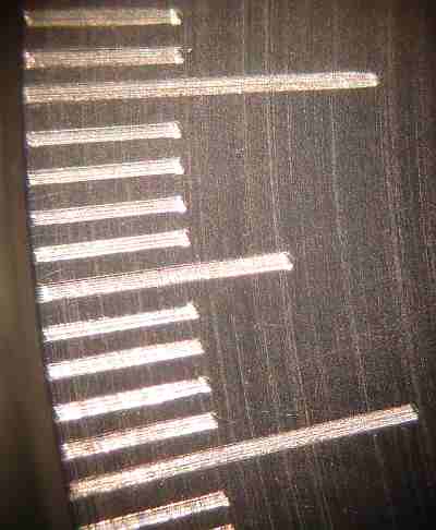 The simple design I came up with works but the graduations are not deep, about 2-5 thou, where I had hoped for 5-10 thou. A deeper line should be possible if I can locate a stronger spring in 1/4" diameter; alternatively, finger pressure could be added during the pull stroke to achieve a deeper line.
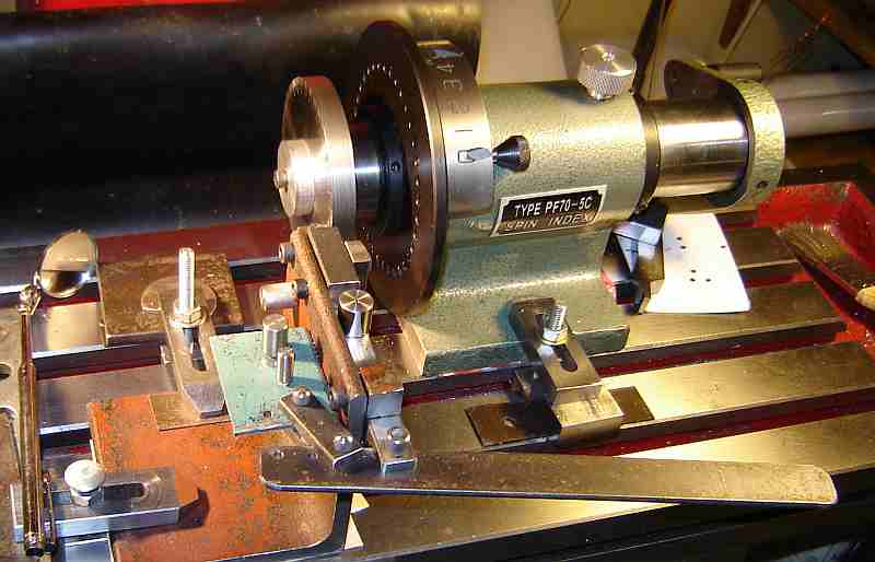
The concept is that a ram, holding the cutting tool is forced against the work by a spring. During the forward (push)stroke the back of the cutter rubs on the work due to spring pressure until the stop is contacted; during the pull stroke this spring pressure forces the cutter into the work to leave the line and as the cutter passes the edge of the work the swarf detaches or becomes a hanging chad that is easily removed. The cutter and pressure spring can be removed and reversed so the cut can be made on the other side for flexibility in application. I expect to use a spin indexer or rotary table for indexing but a similar tool could be fitted to a lathe, where other means provide indexing.
Construction was totally from scrap and all bolts are 10-32 (common practice for my gadgets). A piece of 3.5" angle iron 3.5" long is the main frame. A 3.5" long piece of 1/2" square HRS bar is bolted to this frame as the base for the ram to slide on; all bearing surfaces were flattened and improved on the belt sander. I set the height of this piece so the center of the ram matches my spin indexer (a spacer will be needed for use with the rotary table). 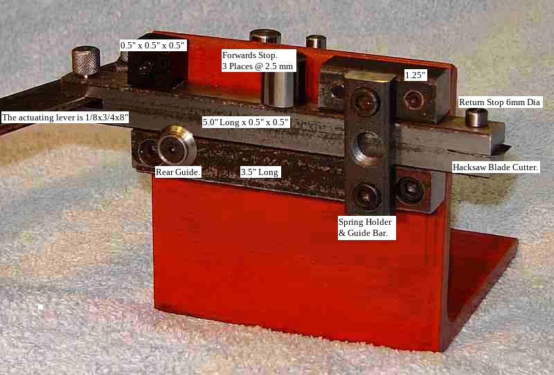 The ram is a 5" long piece of 1/2" square HRS bar, with a 1/8" slit on one end and a 0.027" slit (to fit a section of hacksaw blade)on the other end, each 1/2" deep. A 1.25" long guide of 1/2" HRS above the ram on the cutter end is held by two bolts where the bar is tapped for the bolts; the holes through the frame are slotted slightly to allow adjusting the fit so ram contact is maintained to prevent wobble while cutting. Similarly, a 1/2" cube is mounted on the lever end. A shoulder washer is screwed on (6-32) near the lever end of the lower bar to allow the ram to move horizontally a bit, as needed during cutting.
 The cross piece between the bars (ram end) is drilled and tapped 3/8-24 to accept the spring holder; a similar hole in the frame just opposite allows the spring direction to be reversed by transferring the spring holder. This cross piece is thinned by about 40 thou in its center 0.6" to allow the ram to move horizontally against the spring's pressure.
The actuating lever is 1/8x3/4x8"; the attaching pin is 10-32 size, threaded for a few turns on the end, knurled on the top. The end of the ram is drilled for a 10-32 clearance hole above the slot and drilled and tapped 10-32 below the slot to accept the attaching pin. 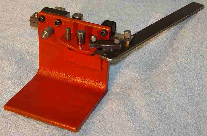 A scrap of small angle iron holds the lever link on the back of the frame, where the link is a 1.25" long section of 1/2" HRS (I was on a roll with this 1/2" bar :-) slit with the 1/8" saw from each end, leaving about 3/16" in the middle. Pins 1/8" diameter with knurled heads are used with the link. The first link hole in the actuating lever is 3/4" from the ram hole; other holes in the lever and angle bracket allow increasing the stroke but are unlikely to be needed in most applications.
Stroke length is set by a stop threaded into the ram so it contacts the top guide to set the forward limit of the stroke. Three stops are needed (1,5,10) so the two not in use are parked in 10-32 threaded holes in the link lever's angle bracket - to avoid losing pieces between uses. I used 160 thou diameter difference between stop sizes but will likely change to 100 thou - a matter of taste.
The spring is contained in a holder 0.400 dia. by 0.75 long, threaded 3/8-24 for 1/4", then drilled out to fit the spring. The contact piece is turned down to fit easily inside the spring with the large end slightly larger than the spring OD but an easy fit into the holder. The contact must not touch the end of the holder when the holder is screwed fully in, i.e. the ram must be able work horizontally against the pressure of the spring without bottoming the contact piece.
The cutter is a 1/2+" long section of hacksaw blade; grind the teeth down, mark and drill the hole for the pin and grind away the excess material prior to the cutting tooth before severing the 1/2" piece with tin snips. 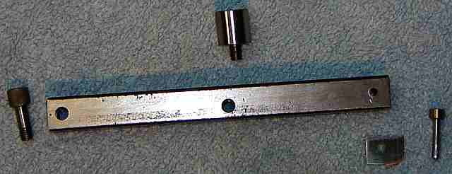 The cutter is ground to look about like a single large tooth for a bandsaw blade: relieved behind the cutting edge with a gullet above the edge. I rough grind on the bench grinder, add the gullet with the Dremel, tidy up with a slip stone. A small pin retains the cutter and keeps it from moving during use; make the pin a good fit in the drilled hole with a slight taper near the end to help force the blade into position. I use a long tapered scriber in the hole to get the blade positioned initially since the blade is an interference fit in the slot.
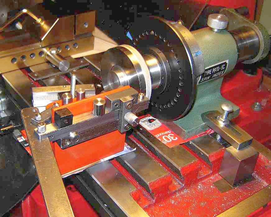
I bolt the indexer and the linerator down on my mill's table using the T slots. Remove the spring holder during setup and set the linerator's cutter so that when fully retracted it is about 10 thou from the work and its movement causes the tip of the cutter to move parallel to the work. I bolt the linerator down lightly with a cardboard pad underneath and tap its frame with a rubber mallet to make fine position adjustments then tighten it down.
Once positioned I install the stroke stop for the 10's lines, then install the spring holder and screw it down fully. Put the spin indexer pin in the 0 position, flip the linerator's handle (twice for a slightly deeper line) advance by 10 degrees, make the next line, etc. until all the 10's lines are done. Then, install the stroke stop for 5's, put the index pin in the 5 position and repeat the above, advancing 10 degrees for each line. Then, install the 1's stop, put the pin in the 1's position, do all the 1's lines, then put the pin in the 2's position and do all the 2's lines, etc. This takes advantage of the ease of advancing the indexer by 10 degrees while keeping the pin in the same number position until all those lines are done rather than moving the spacer and the pin while keeping track of where you are - tough to make a mistake with this setup. Before removing the work from the indexer I inspect carefully - it is possible to doze off and advance 20 degrees instead of 10; easy to recover... unless you've removed the work from the indexer. A full 360 degree dial took a bit over an hour.
Some swarf does stick on the edge of the work but wipes off with a paper towel, i.e. it isn't difficult to remove. There is a little roughness at the edge from cutting so I put the work in the lathe (gripping the stub arbor), spin it and touch the edge with a fine file to remove this roughness.
If you have a comment about this site or its contents, click here.