Last Modified:
Click to Enlarge
I've been interested in clocks for a number of years but have only maintained and repaired our family clocks until recently. With a mini-lathe, my horizon expanded to making bearing inserts and other small items needed for repairs. Major repairs on a
flea market purchase inspired me to build a clock from scratch.
I read several books on clock making and poked around on the web for all the info I could find. I liked the look and gearing simplicity of astronomical regulators but didn't find an existing design I liked so I used my trusty spreadsheet to design my own. The spreadsheet was helpful in verifying gear ratios, gear sizes, conflicts (gears hitting adjacent shafts) etc. My implementation includes ideas from a number of sources including "How to Build a Regulator Clock" by J.M. Huckabee and "Clock Design and Construction" by Laurie Penman.
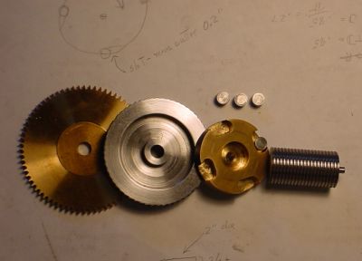
My clock uses aluminum plates with press in bearings as suggested by Huckabee. The bearings are closed on the end where possible with centering via contact on the end of the shaft as suggested by Penman; to accomplish this, the 1/4" bearing shells are made from steel with a 1/8" brass insert pressed in and then bored with a home made D bit. Pinions are barrel type as suggested by Penman. Shafts are drill rod, gears are cut from junk yard brass using information and methods from cSparks site, scaled up for clocks. The bearings and barrel pinions are labor intensive but according to Penman are the most energy efficient approach and therefore should need minimum driving weight.
I bought some aluminum for the plates and built a crude test version of an Arnfield gravity escapement. This was powered by wrapping a string around the shaft; it ran for about 12 minutes before the weight reached the floor. Debugging took about a day, where I changed things quickly by soldering them together -- my understanding of the escapement was sketchy initially, improving as I varied angles and sizes of the parts to get it running. The knock on gravity escapements is that they are noisy and sure enough, the test version clacked each time it advanced. The final version is much lighter, the escape wheel is lighter, the escape teeth are shorter and the result is a modest tick. Adding a case should muffle the sound to nearly inaudible.
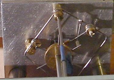
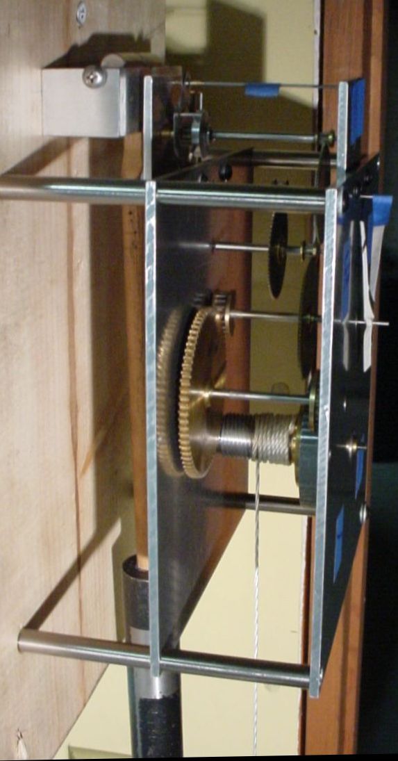
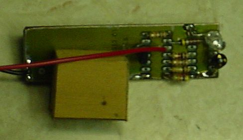
The gear and shaft for the second hand were added with the string wound on this new shaft. More weight was required, of course; run time was over an hour. This picture shows the seconds shaft and some press in bearings; the leftmost bearing is through-drilled for a shaft to drive a hand.
This clock is a work in progress so it remains to be seen whether it will work properly when completed. A number of issues remain to be addressed including temperature compensation of the pendulum.
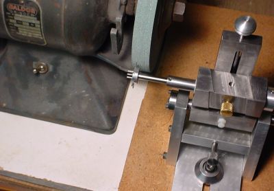
Gear cutting requires a small amount of specialized tooling. I use a 5C spin indexer to hold and index gears for cutting which limits the possible tooth counts to those which divide evenly into 360 (one of the things which led to designing a clock rather than building from a plan). The fly toothcutter is per the previously mentioned method; these cutters take some time and care to make but the material is cheap and they work reasonably well. In my picture you can see the extra hole in the fly cutter used to add relief when making the cutter; the fly cutter is chucked in the lathe while making the cutter. Gear cutting is a slow process with a fly cutter and spin indexer - it takes over an hour to make the 3 passes needed to complete a gear.
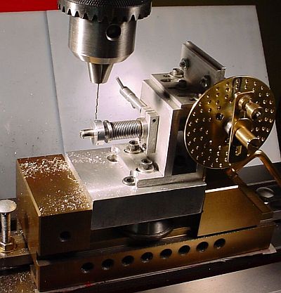
The barrel pinions and escapement were drilled using a small Jeffrie's type dividing head, a gift from a friend. The lathe chuck can't grip the small drills involved so the shaft of a small Jacobs chuck is held in the lathe chuck, i.e. a chuck-chuck. The chuck-chuck scheme works but requires some fiddling to minimize runout and even at that has runout of 1 or 2 thou, generally not a problem with normal size drills but bothersome with drills under 25 thou, common for barrel pinions. I made a small spade bit from 1/8 drill rod by turning the end down to 0.022 for a length of 1/16, hardening it, then grinding it in the Mini-Tinker; this is used to spot the holes which are then drilled with a small twist drill as described earlier.
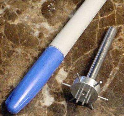
 Cutting trundles for barrel pinions from piano wire was a slow process initially. So, I made a "Whack Bang Wire Cutter" which cuts lengths of piano wire 0.240 long. The bottom part is center drilled 0.250 and has flats machined in the sides to make it easier to hold in the vise. In use the wire stock is inserted in the small hole until it contacts the far side, the cutter/punch is inserted and whacked with a hammer. A wadded paper towel catches the trundles as they exit the cutter. Hardened drill rod seems to hold up well enough in this application to allow cutting quite a few trundles.
I designed and built a depthing tool to aid in placing the shafts.
One of the reasons I chose the Arnfield escapement is the simplicity of the escape gear. My test escape gear uses an aluminum collet to hold the wire teeth. There are 6 radial and 6 axial teeth(drilled as shown); after insertion, the radial teeth were ground to length and then the ends of the teeth were ground at an angle for a clean release from the stop. Grinding was done in the Tinker fixture to provide good control of the process.
The test escapement arms are from scrap tin plate because it could be cut to shape with scissors and solders well. The stop is piano wire ground flat on one side. Several items are adjustable either with a screwdriver or by unsoldering. It took some time to tweak things so it would work but it was surprisingly reliable considering the construction.
I tried to find information on the Arnfield design at CT libraries but haven't been successful to date; Yale has the Horological Journal but wants $20 to copy the 3 page article... Articles concerning the Arnfield Escapement are included in the CD of "Horological Science Newsletter" but I haven't been successful in getting a copy of this either - clock info seems hard to come by for home shop machinists who are dabblers rather than dedicated clockmakers :-)
So, I made a drawing of the escapement essentials in IntelliCAD. Basically, a stick figure showing the lift arms and the escapement suspension point. A circle at the escapement suspension point with radius matching the distance where the lifting arm pivots is informative when coupled with circles with radius equal to the length of the lifting arm centered at the end of the escape teeth which lif the arm. This allows varying the sizes of various pieces and measuring the resulting lift angle without having to bend wires and then tweak things (stop for lifting arm, shape of gravity arm, etc). This was very helpful in improving my understanding of the Arnfield design.
I have developed some ad hoc methods for tweaking my version of Arnfield's escapement plus some observations which other experimenters might find helpful:
On gravity arm construction: the lifting arm should be on the same side of the gravity arm as the pin which drives the pendulum. This takes up any looseness in the bearing supporting the gravity arm -- putting the lifting arm on the other side causes the gravity arm to twist slightly during the cycle and requires extra lift to compensate.
The pictures of the escapement below show the relationships in the first two points. More pictures, eventually...
 It seemed only fitting to use a gravity operated clutch (rather than a click) for winding in a clock with a gravity escapement. So, I cut pockets to hold "gravity pills" where the weight of these pills causes them to wedge between the outer and inner pieces of the clutch -- when turned one way, friction moves the pills into the wider part of the slot, releasing the clutch to allow winding. The outer part of the clutch has a ratchet which engages a pawl to allow the maintaining spring (inside the front of the outer clutch piece) to keep pressure on the gears during winding; a ball bearing supports this piece on the winding shaft, ensuring that it remains concentric with the brass piece which holds the gravity pills. The winding shaft (not shown) passes through the hour hand shaft. The winding arbor is supported by ball bearings front and back.
This gravity operated clutch works nicely. It is silent and nearly frictionless when released, yet locks immediately when direction is reversed. There are two pawls used with the external ratchet for safety and to minimize ccw movement due to the maintaining spring during winding. The pawls are gravity actuated (of course). The maintaining spring is a nearly straight piece of 0.046 piano wire with a hook on the end to catch a pin of the gear; I may have over-done this - the clock will run for about 10 minutes on the maintaining spring. To work on the clock I remove the weight, apply CW pressure with the key and release the pawls.
The first test run (August 25, 2005) using the test escapement and pendulum was marginally successful. It ran overnight but required 9 pounds to operate; the drop is 4.1 inches per day, i.e. 37 inch-pounds per day. This was a disappointment because I tried to make it operate efficiently but it wouldn't run reliably with less weight.
I reduced the diameter of the pivots from 0.062 to 0.035 on the shafts above the hour hand and this improved the efficiency a bit. There still seem to be some "sticky" spots, either because of poor bearings or poorly cut gears. I will install the real pendulum and suspension next to see if this helps. Adding ball bearings on the shaft between the hour and minute hands will follow (the winding arbor has ball bearings already. Then, the escapement will be put into final form or close to it -- this may then be improved by experimenting since the escapement is an interesting thing to experiment with and it is fairly easy to make a couple and swap them.
One benefit of using the complete gear train is that the escape wheel doesn't accelerate as much so the noise is much reduced, more like a normal clock (rather than the original test CLACK!), even without a case. When cased it will apparently be reasonably quiet, much better than I originally expected. Unlike a normal clock, it only ticks once per pendulum swing (the tock is nearly silent).
The changes mentioned above were incorporated: the real pendulum, ball bearings on the shaft between the hour and minutes shafts, a somewhat refined escapement was fashioned from 0.025 piano wire and a new (brass) escape wheel was made. These changes had minimal effect on the operation. I removed the gears and burnished their contact surfaces - again with little effect. I noted that the gear on the seconds shaft was poorly cut and slightly eccentric so I made a replacement and mounted it with minimal runout; this improved operation considerably. 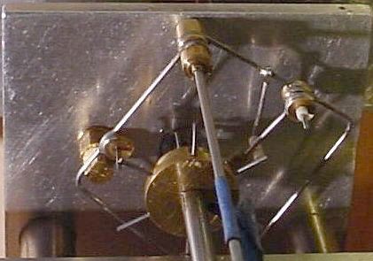
 I then adjusted the escapement by bending the wires to reduce the swing of the pendulum, further improving efficiency. On 25 September 2005 it ran over night on 5.5 pounds, about 23 inch pounds per day. The pendulum swing is still excessive (about +/- 3 degrees, double the desired swing). The left picture is with the pendulum to the left, the right picture with it to the right as seen by the position of the lifting arm.
My version of the Arnfield escapement apparently needs additional refinement in order to reduce the pendulum swing further since I seem to have hit the limit of what I can achieve by bending the wires. I suspect I need to radically re-shape the locking arm to reduce the force required to release it. Then, I expect I'll have to make a similar change to the gravity arm to reduce the impulse in order to reduce the pendulum swing. It took a while to figure out the present problem: the release force required isn't achieved until the gravity arm has gone so far that when it is lifted it still is holding the locking arm up slightly, making the lock unreliable.
A further problem is that power delivery is not smooth, possibly due to imperfectly made gears. The Arnfield escapement is peculiar in that it doesn't seem to skip counts but rather ticks on the opposite side when the gears bind slightly, causing an irregular spacing between ticks when binding occurs. The escape gear advances until it starts to lift the gravity arm but then stops until the pendulum helps to lift it, leading to the delayed tick. This can happen once or several times in succession, depending on unknown problems in my gearing. I have tried various ways of isolating the binding without success,e.g. reduced drive weight and even assembling with only two adjacent shafts, then pushing with a catwhisker mounted on a toothpick but can't seem to locate the binding. The best approach so far is to reduce the drive weight until it stops within an hour or two, mark the gear positions with a pen, then repeat looking for stops which occur at the same gear position.
My present hope is that when the lift of the gravity arm is reduced to reduce pendulum arc, the reduced lifting force needed will allow a normal tick pattern without the occasional irregularities presently observed.
Re-made the locking arm so that it has less of a bend, the goal being to reduce the lifting effort needed to unlock. Re-made the gravity arm using smaller wire to reduce the weight. The lift angle can't be reduced to lower pendulum drive so I tried to reduce the weight instead. The overall effect was minimal; pendulum swing was still above 2.5 degrees. See analysis above for what sets the required pendulum swing - it would have been better to analyze the operation beforehand but better late than never. All testing now is with a 5.25 pound weight = 21.5 inch-pounds per day.
Found a couple gears were slightly eccentric so I remade their collets to improve concentricity. This was a big help toward making the gears run without binding occasionally. 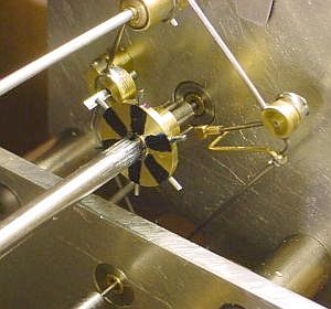 The clock has been running reliably through most of March 2006. The lifting arm needs to be re-made to tidy it up and there are a number of other minor items. But, it runs with reasonable accuracy now - a major step from previous trials. The tick is now quite modest and when it is in a case will be hard to hear, a considerable improvement over the initial clack. I have not managed to reduce pendulum arc to the desired level, the semi-arc is 2.6 degrees. However, the gravity escapement's impulse is nearly constant so circular error doesn't seem to affect the accuracy, at least not with the present simple calibration scheme.
>An optical "Clock Watcher" is under construction and this will use a small computer to monitor and calibrate the clock by detecting passage of stripes inked on the escapement -
The clock has been running reliably through most of March 2006. The lifting arm needs to be re-made to tidy it up and there are a number of other minor items. But, it runs with reasonable accuracy now - a major step from previous trials. The tick is now quite modest and when it is in a case will be hard to hear, a considerable improvement over the initial clack. I have not managed to reduce pendulum arc to the desired level, the semi-arc is 2.6 degrees. However, the gravity escapement's impulse is nearly constant so circular error doesn't seem to affect the accuracy, at least not with the present simple calibration scheme.
>An optical "Clock Watcher" is under construction and this will use a small computer to monitor and calibrate the clock by detecting passage of stripes inked on the escapement - 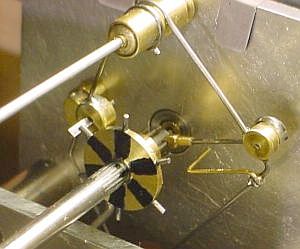 then the accuracy can be explored more thoroughly.
The first picture shows the escapement when the pendulum has released the lifting arm onto the stop, the second picture shows the gravity arm after lift.
then the accuracy can be explored more thoroughly.
The first picture shows the escapement when the pendulum has released the lifting arm onto the stop, the second picture shows the gravity arm after lift.
Found the escape shaft pivot was slightly bent on one end causing the pinion to run eccentrically - clock runs a bit better since fixing this. The tick is still not quite even because occasionally the escape advances more slowly; I can hear this but can't see it or figure out what causes it. Probably another shaft is running a bit eccentric so I'll have to look into that eventually. The backboard had been held in a vise for recent testing but has now been moved back to the side of a cabinet for further testing, something which has made it run better.
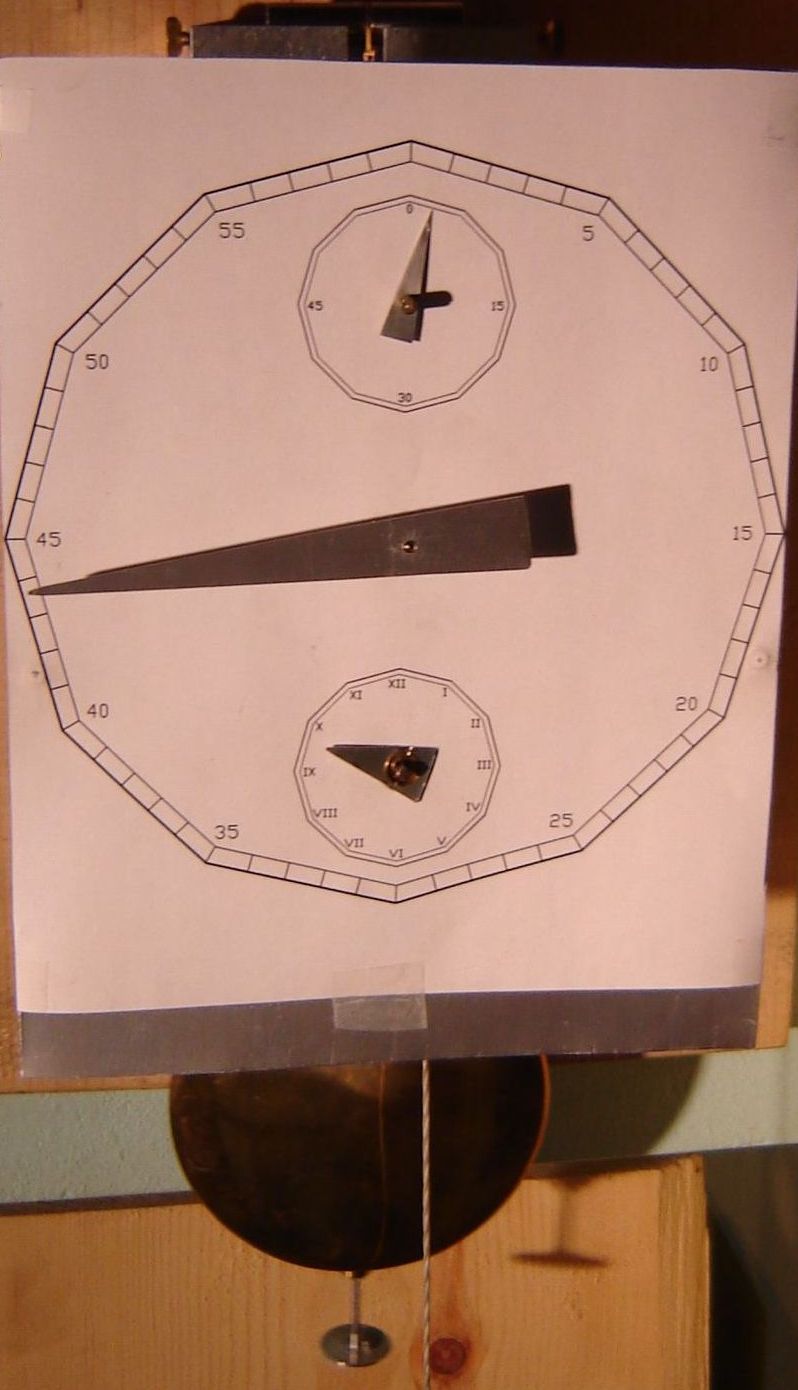
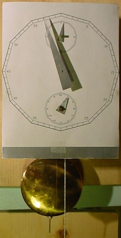
Printed a paper dial and made hands from aluminum scrap. This allows evaluating the operation more precisely than previously. The first day with this showed a gain of six seconds in 24 hours. An interesting point with an astronomical regulator is that the hands are on the going works directly, no motionwork, so backlash does not affect the readout. This allows reading the time to within about 10 seconds from the minute hand.
Adjusting the rate via the pendulum rating nut didn't work well because it was too coarse and unpredictable, plus the clock must be stopped to adjust. So, I added a little aluminum weight tray on the bottom of the pendulum rod; if this works out I will likely make a brass tray to match the pendulum color. I adjusted the pendulum+tray so it was slightly fast, about 7 seconds per day. Weights were made from 1/4" steel rod in length increments of 0.010 -- four so far covering 0.050 to 0.080 plus the initial weight, 0.110, used to estimate the appropriate lengths needed. Weights were stamped with a number representing their length.
Weights are added by dropping them onto the tray with tweezers - not a precision operation but it works OK. Weights are removed by holding a magnet near the end point of the swing; this works very well, the weight jumps off the tray with no visible effect on the pendulum (but see the graph below). With the existing setup of the rating nut, the #8 weight runs -4 sec/day and the #5 runs +2 sec/day so I am in the right ballpark.
Accuracy is now such that I need to complete my optical "Clock Watcher" to properly evaluate the clock's operation. I built and tested the electronics but haven't written the interrupt handler for the microcomputer yet; seems like that is the next step.
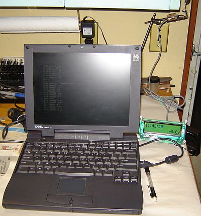 An HCS12 micro+display was programmed to watch the pendulum, optically sensing the weight tray on the end of the pendulum rod.
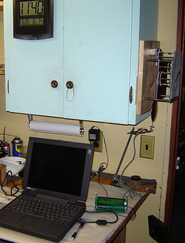
The picture shows the optical sensor I cobbled together from the IR LED of a TV remote plus an optical transistor I had on hand. The IR reflects off the little weight tray on the bottom of the pendulum rod. The HCS12 times each swing (in microseconds) and averages the result. The time of day is displayed based on counting the swings. The number at lower right is the filtered and scaled rate error in sec/day.
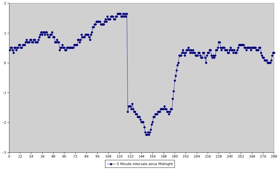
This rate error is stored every 5 minutes in an array that can be listed to see the variation in rate during the day due to temperature and pressure changes. So far, the clock is less stable than I expected: the rate wanders by up to 2.5 seconds/day. I've only been monitoring for a short time so far and expect to learn more about what causes this variation. Another thing I found surprising is that when disturbed it takes over an hour for the pendulum rate to re-stabilize. A picture of the overall setup including the Radio Controlled Clock I use as my time standard. The portable PC is used for software development and to view the rate array but is not needed for simple monitoring of time and rate since they are visible on the LCD.
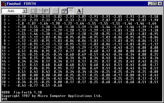
Here is an early screenshot of the rate array with hours in the left column, sec/day every 5 minutes in successive columns; at 10:30 I removed a small weight from the tray to increase the rate by approximately 1 sec/day; the screenshot was taken at 17:21. Note how the rate increases for 40 minutes, over-shooting to +0.95 and eventually stabilizes at +0.34 about 13:00, i.e. 2.5 hours to stabilize: graph of rate from 10am to 2pm. This with the tiny weight picked from the tray using a magnet so there was minimal disturbance to the pendulum. The overshoot was a major surprise to me, I expected an exponential decay rather than a damped sinusoid; I don't understand where the energy is stored to allow this overshoot... This overshoot may have been an anomaly, a subsequent weight change did not overshoot. The weight change from #5 to #4 took 40 minutes to stabilize, where the steep discontinuity is the point new data is being added to the ring buffer -- which always contains the last 24 hours of rate data taken every 5 minutes (round and round we go). Eventually I'll add a snapshot'er to the tick handler so a copy of the 24hr array is made at 2359 each day; then the discontinuity will occur at the end and not be so obvious.
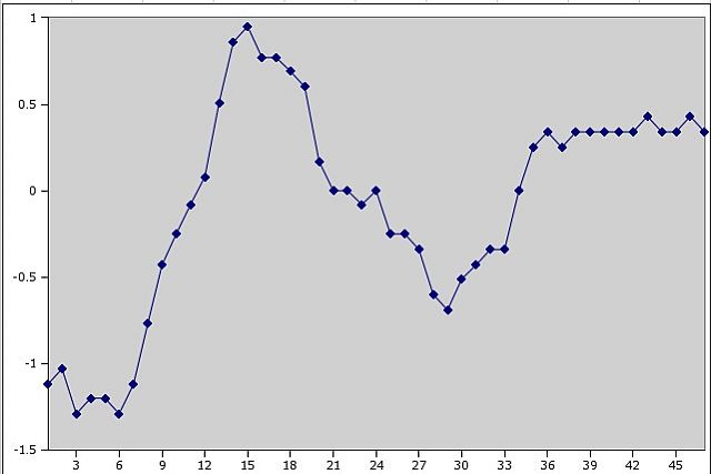
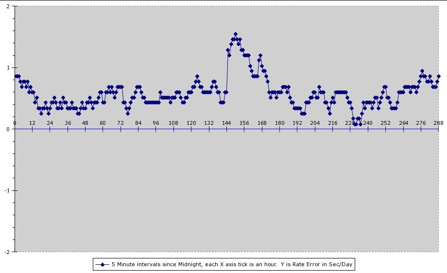
Here's a graph shot taken at noon (i.e. the discontinuity is in the center) where I didn't touch the clock or Watcher during the 24hrs shown. The average rate error was +0.58 sec/day and the std deviation was 0.24 sec. I may increase the weight slightly but I want the clock to gain time slowly because I intend to add a control that allows easily stopping the escapement advance temporarily. This should provide a quick and easy way of synchronizing to actual time from the radio clock. I haven't figured out a way of adjusting the time forward easily so the simple approach is to ensure it is gaining slightly. The rate variation shown in this chart is from temperature and pressure variations, noise in my measurements, drift in the computer's crystal, and random variation in the clock mechanism itself; I doubt I can improve on this by much so it is time to build a case for the clock :-)
It will be interesting to see how long it takes to stabilize after a serious disturbance to the pendulum - this may explain my lack of success in adjusting the pendulum via the rating nut where the pendulum was stopped and then restarted. I adjusted it once a day and the disturbance from restarting may have induced more change than the adjustment -- speculation so far, it will take some time to gather info to support this theory.
The HCS12 uses a multi-tasker with the tick handler task running in the background, easy to do in FORTH and it makes tweaking the print program easy because it can be replaced without disturbing the Watcher operation. The tick handler could use some revisions too so eventually I'll have to stop the Watcher and replace the firmware but I've learned a lot about my clock's characteristics already from the captured data. The crystal for the HCS12 has an apparent error of about 0.003% based on comparison with the radio sync'ed clock so the Watcher program now compensates for this.
For now, I calculate average rate error for the prior 24 hours and the Std. Deviation of the rate in this period; this is easy to write down and tells quite a bit about the clock's operation. I added a two line FORTH program to plot the last 2 hours of rate data in TTY mode to provide an instant overview of the recent data (easier than capturing the data and using a spreadsheet). It's been a while since I programmed in FORTH, I had forgotten how much fun it is and how compact the programs are for this type of application.
The rate seemed less stable during times when I was in the shop. Apparently, I rest my feet on the lower shelf of my bench and may cause a little movement of the bench which is transmitted through the wall to the clock; I'll try to keep my feet off the shelf in the future. The door is adjacent to the clock so I try to remember to leave it open because it may affect the clock from the bump when it closes. Clearly, the setup is touchy when looking at rate changes on the order of a second per day.
The time displayed by the Watcher tracks the time shown by the clock hands, suggesting the escapement is not skipping or hanging -- both these faults have occurred in the past. I inked lines on the escape wheel and built the watcher optic so it mounts on the rear plate for monitoring of the escape wheel. I tried this and found far more "noise" on the measurements from inconsistencies in the inked stripes (of course) but also because the gears don't advance the escapement perfectly, i.e. each advance can vary by hundreds of microseconds. While I could cook up a more elegant noise filter, a trial of pendulum sensing showed the measurements to be far less noisy. Unless the Watcher time display vs clock hands doesn't track I'll continue using pendulum measurements.
If you have a comment on my site or its contents,
click here, scroll down and click again. (This setup reduces my SPAM from address harvestors)
This page was by John Moran, tyro machinist and HTML tweaker.