


* GadgetBuilder.com * Last Modified
Click to Enlarge
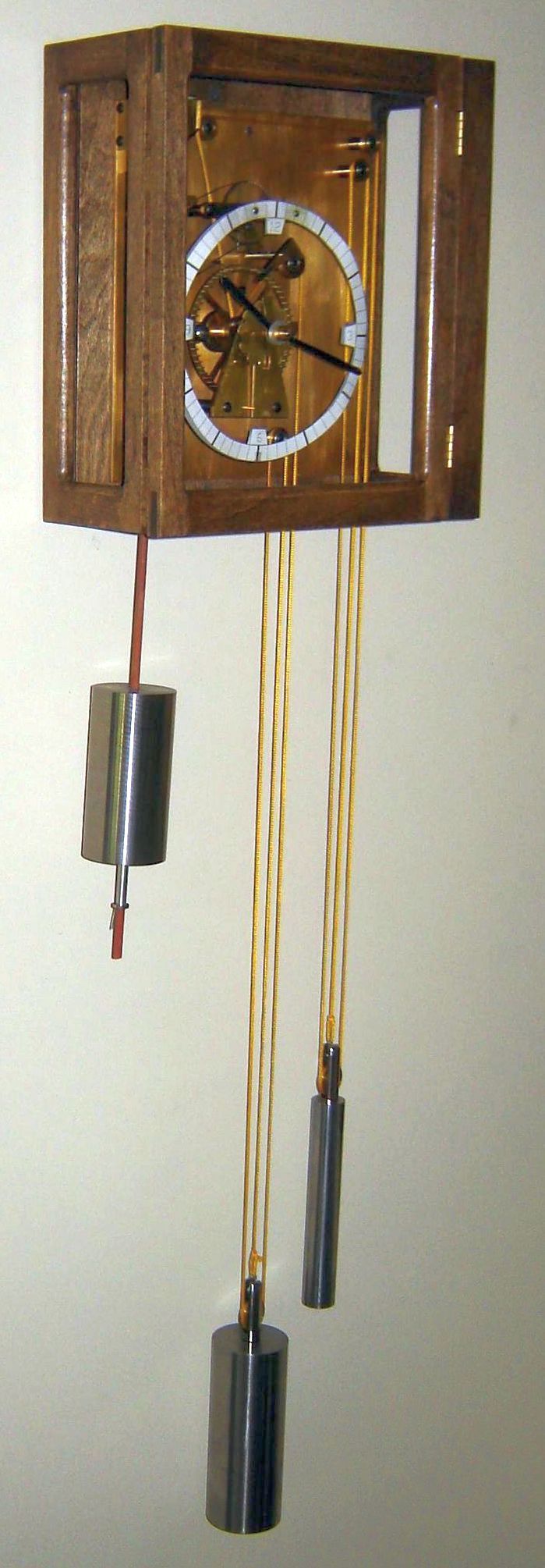
After reading Dr. Philip Woodward's "My Own Right Time", I was inspired to build a copy of his gearless clock. John Wilding's construction book for this clock provides details that simplify construction although (as usual) I made some "improvements". The minimal number of parts and their unusual construction made this a delightful project, enhanced by the fact that this clock obviously wanted to run. John Wilding also published the plans in "Model Engineer" magazine as a series of 8 articles in volumes 192 and 193 (see their on-line archive $).
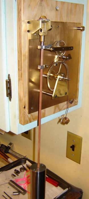
The picture above left (with yellow string replacing the stylish pink drive string) was taken during a trial of the weight/drive system. The temporary dial is paper, just taped in place for evaluation. The pictures above show a practice case made from poplar, done to improve my (non-existent) woodworking skill and the purchased chapter ring. Morning sunlight reflects off a tiled table in our living room and through the clock producing an interesting shadow on the wall. This shadow occurs for a couple weeks around spring solstice - leaves are still on the trees at fall solstice so no shadow then. This clock may never be complete... but it is getting closer, always a few little details left.
Dr. Woodward's gearless clock design is novel in many ways. It is a modular design where the various functions are easily recognized and connect to other functions in a way that is ingenious but clear on careful inspection, leaving the observer with a "wish I'd thought of that" feeling as each facet of its operation is understood. Some of the connections between functions are made up of wires with counterbalance weights so gravity returns them to their default position - a most unusual implementation method in a clock. This design strips away the mechanical complexity of a typical clock, leaving the essential details implemented in an unconventional but very functional way; it's entertaining to watch it work and a challenge to understand the operating details.
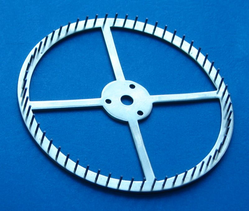
The pendulum in this clock connects directly to a ratchet wheel via a pawl which indexes this count wheel for each swing of the pendulum; a backstop pawl ensures the wheel indexes in the correct direction at each swing. There are 48 teeth on this count wheel, one of which is deeper than the others; this deep tooth causes the pawl to move a deflector lever connecting to the minute module.
The minute module has a hook connected to the pendulum, where the deflector lever noted above depresses this impulse hook to engage a pin on the minute wheel. The timing is such that the hook first pulls the minute pin wheel backward a half minute, releasing the escape. This allows the pin wheel to then impulse the pendulum as the pin wheel moves forward by 1.5 minutes, limited by the escapement; pendulum inertia carries the hook a little farther, releasing the hook. This hook and the lever which originated the pendulum impulse are both counterbalanced so they assume their disconnect position until the count wheel completes another turn. This gearless clock is unusual in that it impulses the pendulum only once a minute; the interaction of the impulse hook and the escapement is most ingenious, producing a sound similar to that from a common pendulum clock arming to strike.
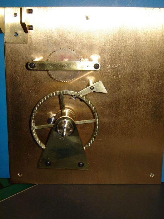
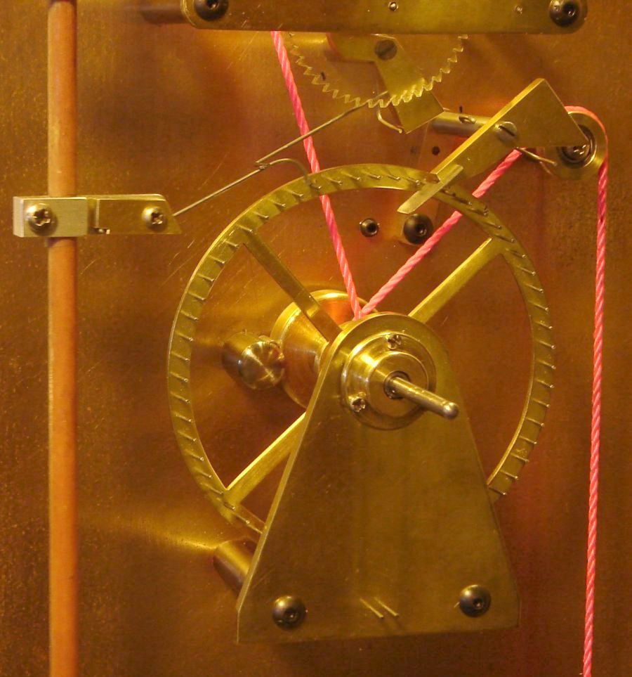
The escapement remained a bit of a puzzle to me until I built it and saw it operate. Each minute the pin wheel is pulled backward slightly; this releases the pin captured by a lip on the counterbalanced escape so the escape pops upward, landing against the next pin; this pin then slides along the shelf as the pin wheel rotates until it drops through the slot and is captured by the lip, completing the cycle. The escape is shown in a picture below but it is best to see Dr. Woodward's book for a good explanation - or just build one...
The YouTube video of the escapement's action shows a few seconds before and after an impulse to help understand how the escape works. The ticks heard in the background are from two other clocks in the room but the impulse sound from the gearless escape can be heard clearly. The string has a black thread running through it allowing the (small) movement of the weight at impulse to be seen at the right edge of the picture.
Power to drive the clock is supplied by a weight attached to a string wrapped around a pulley on the minute arbor. This clock isn't "wound" in the strict sense - the drive weight is simply lifted and the resulting slack in the string is taken up by a second (jockey)weight. This second weight is a fraction of the weight of the drive weight, causing the string to bind in the pulley, much as a bollard is used to amplify friction when controlling a ship at a pier. Pulleys are used to direct the drive string path. While winding by lifting the weight is quick and easy, lifting the weight too rapidly can pick the string off the pulley so one must proceed gently while "winding".
The daisy wheel motion work module is driven by the minute shaft and is easily removable by taking out the retaining taper pin on the minute shaft.
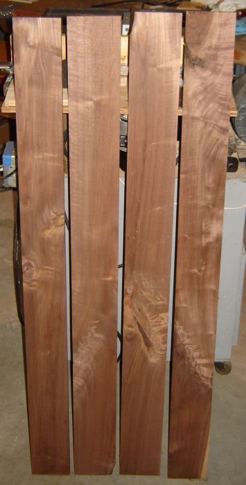
I'm still working on minor details. The biggest thing left is to build a walnut case for it. This clock is a work in progress; some pictures and text follow, more may be added later.
As with many of my projects, this clock was made mostly from scrap plus a few bits of purchased material. I had a nice 4" long piece of 1.25" polished stainless tube so I filled it with chopped up lead; weight was 2 pounds - I used this initially as the pendulum (shown in some test pictures) even though it was only half the weight specified by John Wilding. In many clocks pendulum weight isn't critical but here it is because this clock uses larger, less frequent impulses to keep the pendulum moving. With this lighter pendulum storing and dispensing this energy, the single impulse each minute causes a larger than acceptable change in pendulum swing. When the swing is too large the pawl gathers two teeth on the count wheel for a couple cycles after the impulse causing the clock to gain time. Reducing the impulse enough to eliminate this makes the clock unreliable. So, I found a piece of 2" steel round and made a pendulum to John Wilding's plan - makes operation reliable and tolerant of reasonable variation in drive weight. With the original light pendulum the decay in pendulum swing between impulses was easily seen but it isn't obvious with the heavier pendulum.
The initial pendulum rod was fiberglass composite with the glass fibers parallel to the length; this was eventually replaced with a carbon fiber rod for reduced temperature coefficient. Carbon fiber, according to what I found on the net, can have a positive/zero/negative temperature coefficient dependent on how the fibers are laid up - the rod I purchased from the hobby store seems to have a positive coefficient. The parts holding the count and impulse pawls were from aluminum except the counterbalance for the impulse hook is brass - my notion was to minimize the weight above the pendulum which the fiber rod and aluminum parts help accomplish. The aluminum pawl holders didn't look good on the pendulum rod so eventually I replaced them with brass holders. In replacing the count wheel pawl I used 0.025 music wire and added a partial counterbalance to minimize the sound as the pawl drops.
A threaded section with a rating nut supporting the pendulum, as suggested by Wilding's plans, would add additional temperature sensitive metal lengthening the pendulum rod. My thought was that this would make temperature compensation more difficult so I opted for the method below where the main item requiring temperature compensation is the suspension spring - plus the carbon fiber rod has a positive temperature coefficient. A rating nut works well for accuracy of a minute or so per week but I wanted better accuracy than this - which requires much more fussing.
My assumption was the pendulum period would lengthen with increasing temperature so I drilled the top half of the pendulum to just pass the rod and drilled the bottom half larger so a thin aluminum tube surrounding the rod could be installed. A pin through the pendulum rod 2" below the pendulum supports the aluminum tube; by supporting the pendulum at its center, expansion of the pendulum itself with temperature should be neutralized so the aluminum's expansion need only cancel the suspension spring and pendulum rod expansion (it says right here :-) The thin aluminum tube was filed to length (1 thou = 2.8 seconds) to set the rate a few seconds a day slow; washer-like shims below the aluminum tube are then used to coarsely adjust rate. Adding small weights on top of the pendulum will raise the pendulum's CG and speed it up slightly - easier and more precise than a rating nut. Similar to the way Big Ben is adjusted...
This is a nice theory that compensates for part of what occurs in practice. Slow changes in temperature are handled reasonably well by this but my clock is mounted on an outside wall that faces west (heated by afternoon sun and cooled by winter winds) plus we use setback thermostats so the room temperature can vary by 20F within a couple hours in winter; further, we have hot water heat and a radiator happens to extend directly under the clock, further confounding the issue. In summer, temperature swings are slower but can be larger, perhaps 35F in a day.
Transient temperature response of the pendulum system is difficult to evaluate in situ. The upper end of the pendulum rod, including the suspension spring, is enclosed in the case - reducing the rate that ambient temperature affects it. The lower end of the pendulum rod, including the pendulum and the aluminum temperature compensator, is outside the case exposed to ambient room temperature and also moving which aids heat transfer. In addition, the aluminum temperature compensator is partially within the pendulum so its temperature response to ambient is further muddled.
A better location or a full size case with temperature control aren't going to happen so approximate compensation for slow temperature changes plus setting the rate so it averages out on a weekly-to-monthly basis seems like the best approach.
Rate adjustment is a successive approximation process. The first approximation puts the center of the pendulum about 15.5" below the top of the pendulum mounting bracket. A cross pin is positioned about 2" below the bottom of the pendulum; this pin supports the pendulum via the temperature compensation tube. Coarse rate adjustment was done by filing the aluminum temperature compensation tube to length (as noted above). A steel washer with a recess to prevent the cross pin from moving supports the tube.
 It's easy to go a little too far when filing the tube to length. To raise the pendulum a bit one adds a washer-like shim under the tube. These shims are trickier than they first appear. Initially, I would calculate the required thickness, make an aluminum washer about that thick, then rub it on fine sandpaper to fine tune the thickness. Unfortunately, the thickness wasn't uniform so it wasn't clear exactly how much it raised the pendulum - this became more of an issue as the rate error decreased, of course. I accumulated a fair number of shims pursuing this method and always seemed to need one more. Eventually, I filed more off the tube so the shim thickness needed was about 0.060" -- this allowed using two shims in the 25-35 thou range to make up the needed thickness. A small pot chuck was made to simplify making shims. This chuck grips 0.350" diameter items for a depth of 0.020" so shims are now cut from the washer stock to be about 0.040 and then their thickness is adjusted in the pot chuck. The pot chuck is also used to grip the shims while polishing on a piece of fine sandpaper laid on a flat. There is still some variation in thickness but it is now only a couple tenths, where 1 thou = 2.8 seconds per day.
With the rate set a second or two per day slow, rate can be increased in tiny increments by adding small weights on top of the pendulum. These can be dropped on with tweezers or swept off with an artist's brush for minimal disturbance to the pendulum.
Initially I built the count wheel and deflector per John Wilding's book, other than revising the deflector stop for simplicity. As time went on (pun) I realized that the design of these parts made set up and tuning of the clock more difficult than necessary.
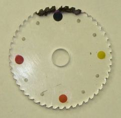 The count wheel was changed to have small notches rather than fully formed teeth - only one tooth was fully formed (to catch the deflector once a minute). This made it far easier to adjust the count pawl for proper operation. The picture at right shows the revised count wheel with ink near the deep tooth to improve contrast.
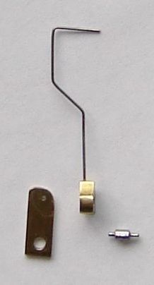
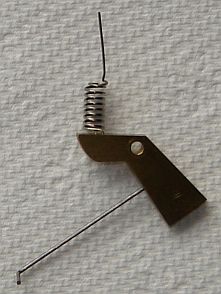 I added hints on setting the clock up based on my experiences and as part of that described the operation of the deflector in detail. The description makes it clear that once the hook contacts a pin then the hook cannot easily deflect further so the force from the count pawl on the deflector rises sharply - this caused a groove to be worn in the area of the deflector wire that contacts the hook. I added a coil spring section to the deflector wire the count pawl contacts to limit the force applied to the hook - see the picture at left. This makes the clock more efficient (pendulum arc increased), much easier to adjust, and the impulse action is slightly quieter.
Eventually I changed the design of the backstop pawl to make it more symmetrical with the count pawl and easier to adjust (also linked above).
Builders considering construction of this clock would do well to consider all three of these changes - they make it far easier to achieve reliable operation. At the very least, include the deflector spring.
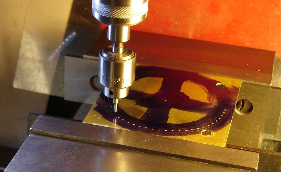
The escape pin wheel is the most difficult part to build in this clock. Fortunately, my mill's DRO has a "bolt circle" function which made it straight forward, if tedious. Here, the 60 holes (one for each minute) are being spotted using a shop made 0.022 spotting drill, spade type. This was followed by drilling with a 0.029 twist drill.
Click to Enlarge
The escape wheel was pinned using a shop made tool having a hole 2 thou larger than the 0.031 pin. The magnet on the side of this tool holds the pin in the tool until it is set. When the pins were pressed through the wheel, the steel block stopped them at a uniform point so cleanup of the back per Wilding's book wasn't needed. I cut all the piano wire pins to length in the "whack-bang wire cutter" from my prior clock project, then held them in a pin vise mounted in the 7x12 chuck, filed the ends flat and chamfered them, (the insert end more than the other) with a diamond file.
The completed escape pin wheel, OD= 3.125".
Escapement test - the escape is gravity operated so moving the pin wheel by hand cycles the escape. The count wheel/backstop and pendulum connection were tested previously (no picture) where the pendulum will operate the count wheel for a little less than 2 minutes.
A test driven with weight hung from pin wheel, runs for 15 minutes - until the weight hits the bottom support. This simple arrangement (a nut, washer and bent paper clip) allowed adjusting the basic operation of the clock without the complexity of the weight drive system. This test weight is also a convenience while threading the drive string through the works, keeps the escape from jiggling around - but isn't needed once the sprag is added.
Ran the drive section for a couple days without the motion work, then added it as shown below. Surprisingly, the motion work didn't seem to affect operation - pendulum swing didn't diminish due to the added load, as I thought it might.
The weight drive required some tinkering to get it right although the weights per Wilding's book provide a good starting point. I used 1.5 pounds for the drive weight and 120gm for the jockey weight. The nylon string slowly slipped on the pulley so I increased the jockey weight but it needed about 1/3 the drive weight to stop slippage. Winches on sailboats often have roughened surfaces in their scaled up application of this principle so I roughened the sides of the "V" drive pulley to improve traction, which worked well. This was done by mounting the pulley loosely on a small round then rolling the pulley on this shaft using pressure on a needle file in the "V"; this left an imprint of the file teeth on the sides of the "V", not deep but enough to improve grip. Fine carbide paper was then used to ensure there weren't any sharp snags left by this operation.
The clock takes some time to stabilize operation after start-up. Initially, one deflects the pendulum so the impulse hook is moved one escape wheel pin space from rest and releases it. It then takes several impulses (minutes) for the pendulum swing to reach equilibrium. Generally, after 3 or 4 impulses one can tell from watching the count wheel pawl and backstop pawl vs the teeth whether the impulse is correct - this from several hours experience watching how it works, of course.
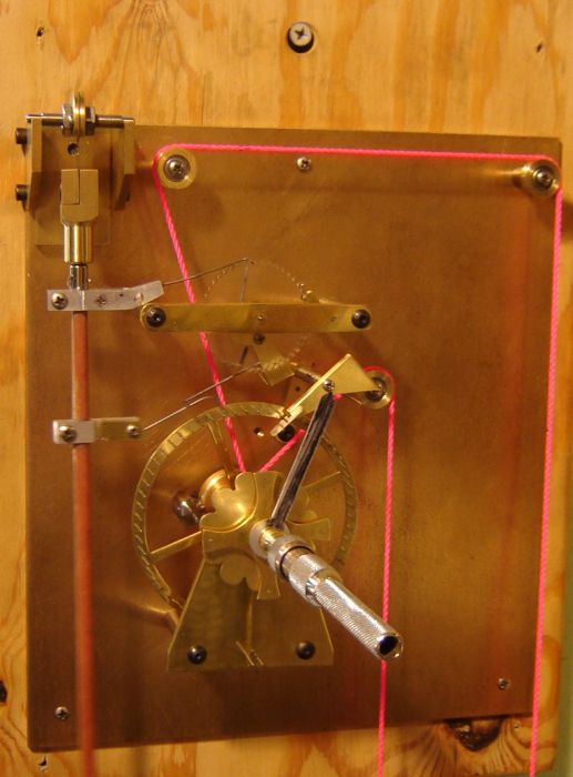
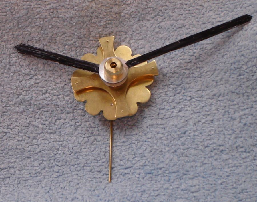
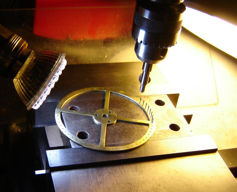
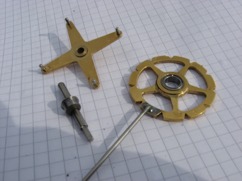
This picture shows the daisy wheel motion work assembled with the temporary hands in place. This emphasizes the modular nature of this motion work, where taking out one taper pin allows it to be removed as a unit. A video of the daisy wheel motion work.
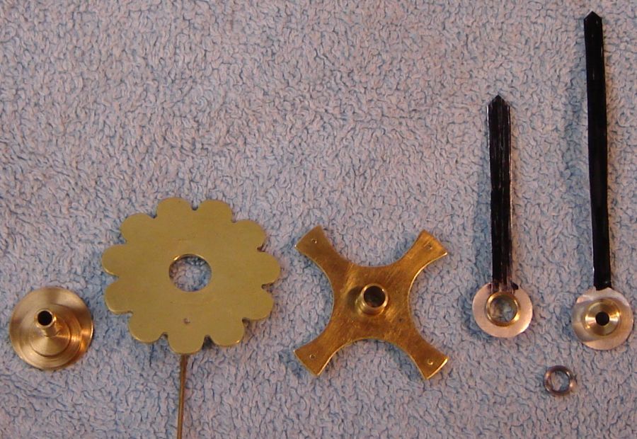
Below is the daisy wheel motion work partially disassembled. On the left, the minute collet with the cam and spacer; I lightly press fit the cam rather than using a setscrew. Next is the daisy wheel - the stem was soft soldered in place. The hour collet with the pin wheel, again pressed on. The hour hand collet and finally the nut for the minute hand. The aluminum hands for testing just press in place so they're not really secure. I added a spacer to take up slack between the hour collet and the minute nut, slack caused by mis-reading Wilding's dimensions for the hour collet. Never having seen a daisy wheel motion work previously, it was an education watching this one operate. While it looks simple and there aren't many pieces, I made 5 cams to get the throw right before filing the daisy petals to fit... as the world's slowest machinist, it took over a day to make these few parts. Again, the DRO's bolt circle function was a big help.
A nice feature of the daisy wheel is that time can be set forward or back simply by turning the minute hand, unlike some clocks where time must always be adjusted forward. Little force is needed to drive the daisy wheel so the light clutch friction to the minute shaft is easily overcome while setting.
Initially there was an issue with the daisy wheel binding occasionally so I filed as required to eliminate these binds when they occurred; there were 4 stoppages over 2 days. When turned by hand the daisy wheel never bound up so this seemed the simplest way to find and eliminate the binding. I had visions of months of intermittent problems but it has now run for over 2 months without stopping unexpectedly so it seems to be settled (I have stopped it for short periods to work on it during this time, of course).
Update: The daisy locked up again on 1 October 2010. Close examination found a burnished area on one daisy petal from a pin rubbing; I filed this area down a few thou and we're off and running, again. This brought to mind a picture of a daisy wheel with abbreviated petals sent by Anthony Adams in 2007. Clearly, he found that the petals weren't necessary (just the "V's") and the petals have been the main issue with my daisy wheel. Having fully formed petals makes it easy to point out the daisy wheel to visitors but slightly smaller petals might have simplified debugging. It was difficult to figure out whether the petal or the "V" was the problem when filing to shape initially so I enlarged the "V's" a bit and this causes the hour hand movement to vary slightly - not obvious unless you're looking for it but check the video above for this effect.
The pins that hold the daisy stem vertical while allowing it to move up and down were set slightly too far apart. This allows the escape release to wiggle the hour hand more than necessary so I Loctited 1/16" brass tubing over these pins to take up the excess space - not obvious that it is a patch and it reduces the wiggle considerably.
A maintaining work is used to ensure a clock operates normally while being wound, where winding removes the driving force temporarily. The escapement used here, like Harrison's Grasshopper, will malfunction if drive is removed while winding. This maintaining work can provide one impulse so winding can proceed without regard to the impulse time; it will provide a second (smaller) impulse but this isn't sufficient so the count wheel will stall about 45 seconds later.
Initially, my maintaining work wasn't reliable, stopping the clock after an hour or two. I added a ball bearing but it didn't help so I changed the spring from 0.040 to 0.032 music wire. (The ink drawing of the spring is because I installed it backwards... more than once.) 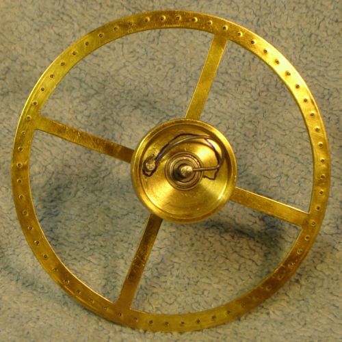 This worked longer -- the sprag clutch scheme activated and released as expected but stopped within a day. The underlying problem was the pulley slowly migrated on the shaft until the sprag wheel contacted the sprag holder, adding friction; a spacer between the drive pulley and pin wheel resolved this. Unlike most clocks where the maintaining work activates only when winding, this clock also activates it once a minute (each time the pendulum is impulsed) so it really gets a workout.
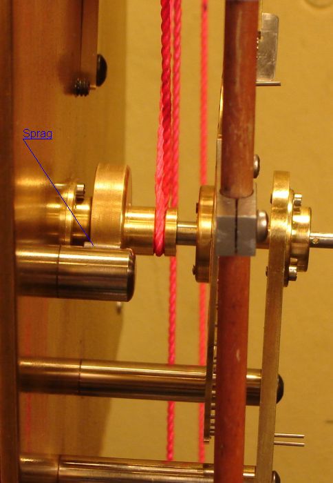
Dr. Woodward used some of John Harrison's concepts while designing this clock but used a different, more complex, maintaining work. My design is closer to Harrison's maintaining work, consisting of this spring plus a sprag clutch (in place of Harrison's ratchet and pawl) that prevents the drive pulley from turning backwards as the clock is "wound". This required separating the drive pulley from the escape wheel on the shaft to drive the main shaft through the spring shown. The large diameter section is the bearing surface for the single sprag which is held by a short steel pillar with a flat on the side (see pictures below); the sprag is the small cylinder which rolls between the two. The flat angles toward the large diameter section so the small cylinder sits between them; when the arbor rotates clockwise it lifts the sprag upward slightly so it rotates in place with little drag. When the arbor attempts to rotate counter-clockwise the sprag wedges between the flat and the large diameter section, preventing reverse movement and allowing winding. (Both the sprag and the large diameter section were rolled on a fine file to add a little texture for improved traction.) A ratchet and pawl used in this type of application is often called a click; this sprag clutch is... a clickless click ;-) I added a retaining clip (not shown) over the sprag because it falls out when the clock is laid flat to work on it.
Update: The sprag became unreliable after 5 months, occasionally failing to prevent indexing of the escape during winding. Examination showed the roughness from rolling the mild steel sprag on a file had worn away. I turned a new sprag from drill rod, knurled with a fine straight knurl, and hardened. If this wears then the steel pillar holding the sprag will be replaced with a brass pillar.
My design hides the maintaining spring, unlike Dr. Woodward's where all of his works, including the maintaining works, are visible. John Wilding used a manually activated maintaining work while I prefer automatic. My notion is that this maintaining work fits well with the simplicity of Dr. Woodward's clock... this from an engineer who got a D in Art Appreciation :-)
In retrospect, a maintaining work is a complication to the elegant simplicity of this clock. Impulse occurs only once per minute so it is possible, via observation of the count wheel, to see when the impulse will occur and avoid winding during that time. It is easy to hold the pin wheel against the escape with a finger while winding. Winding takes about 35 seconds with my clock for a run of 5.5+ days.
Update2: (January 2014), I found that my maintaining work can cause the clock rate to vary several seconds per day so I removed the sprag and simply hold the pin wheel while winding the clock.
Update3: (April 2014),  Replaced the maintaining work with a "winding aid" . This winding aid prevents the escape from activating while winding, as it would when the weight is lifted. The winding aid requires the user avoid lifting the drive weight when the impulse is about to occur - this is easily judged by noting the position of the deep notch in the count wheel. The winding aid applies pressure to the pin wheel when the string goes slack as the drive weight is lifted.
Unfortunately, the winding aid adds some visual clutter to the simplicity of the works. It is less intrusive than it appears in the picture at right because it is partly hidden behind the dial and the case (which were removed for the picture). There is a 3 turn torsion spring (0.017" wire) between the part that holds the arms and the knurled washer; the knurled washer is turned CCW until the arm nears the pin prior to the pin the arm will contact. Then the screw is tightened to lock the knurled washer in place.
The weights suggested by John Wilding are about right for my clock when adjusted for my pulley setup. I used 3 lines to the moving sheave to reduce the weight's travel to 1/3. All the pulleys have shielded ball bearings. The jockey weight is 1 pound so the force is 1/3 pound. 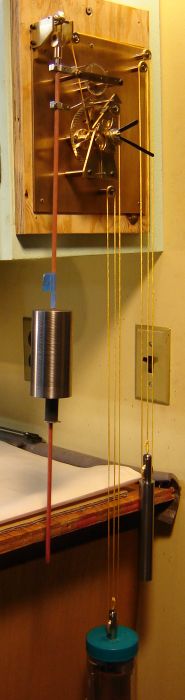 The drive weight is 1.5 pounds (for force, subtract the jockey force) with a payout of about 19 inches per day or about 22.3 inch-pounds net per day, about normal for a regulator clock. The drive force is about 4.5 times the jockey force - the jockey weight might be decreased by experimenting but is acceptable as is and provides a margin for change over time.
I tried several diameters of mono-filament fish line as well as a braided fish line but the light line slipped through the drive pulley unless the ratio of jockey weight to drive weight was increased dramatically. Heavy mono-filament (60 pound test) didn't slip but held so well that it wasn't possible for the jockey weight to do its job. The pink nylon string is 62 thou diameter and far stronger than necessary. Braided or mono-filament rather than twisted line is required because twisted line causes the three lines to the weights to twist together.
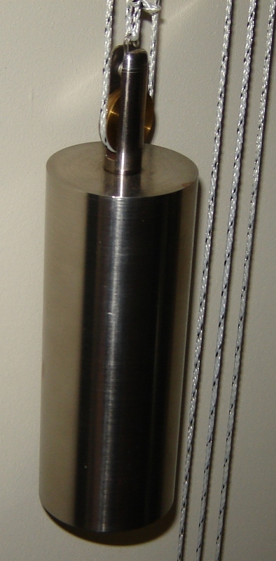
I found #18 braided builders line by Starrett at Sears. It was available in bright yellow or garish pink; these colors are deliberately bright for visibility at job sites but the yellow goes reasonably well with brass, see picture at right. This line is flat rather than round but grips well in the drive pulley. The picture shows my classy test weight (would go well with the pink string :-), a peanut butter jar containing 4.6 pounds of steel. Both the drive and jockey weights have a moving sheave with 3 lines; fall is about 6.5 inches per day. A drive weight has since been turned from the same steel round which supplied the pendulum.
The pulley holders on the weights are 1/2" steel round; the pulleys are smaller than the more traditional ones used by John Wilding, closer to those used by Dr. Woodward. I didn't think through machining of my design very well: the slot to hold the pulley is 0.200 wide and 1.44 long. The only slitting saw I have with appropriate diameter is 3/64" thick so it took 4 passes at 10 minutes per to make each slot.
I expected to use mono-filament for the drive line so didn't cut the pulleys very deep. The pulleys worked fine with mono-filament or the round (pink) string but the flat yellow string ran off the pulleys so I made a mandrel to hold them and re-cut them deeper.
The blue tape above the pendulum holds a reflector for use with the Clock Watcher's optical sensor.
I used the Clock Watcher's setup mode (displays pendulum period in microseconds) to quickly tweak the rate within a couple minutes per day using shims under the pendulum. The original Clock Watcher software was written for my earlier (unsuccessful) clock which had a 1 second pendulum. I took advantage of that one second pendulum to simplify the software and this came back to bite me -- I had to change it to handle this clock's 1.25 second pendulum. Fortunately, it was easy to revise the program so pendulum period is a parameter - the Watcher's display is affected in that it updates on each pendulum swing so every fourth swing it updates by two seconds.
I synchronize the Watcher's display with the radio controlled clock, then the gearless clock's hands are set to the minute and the seconds are synchronized by lifting the count wheel backstop to stop the count wheel without affecting the pendulum. When everything is sync'ed I watch either the Watcher or radio clock's display and listen for the gearless escape to trigger on the minute, this sound makes it easy to get everything set properly.
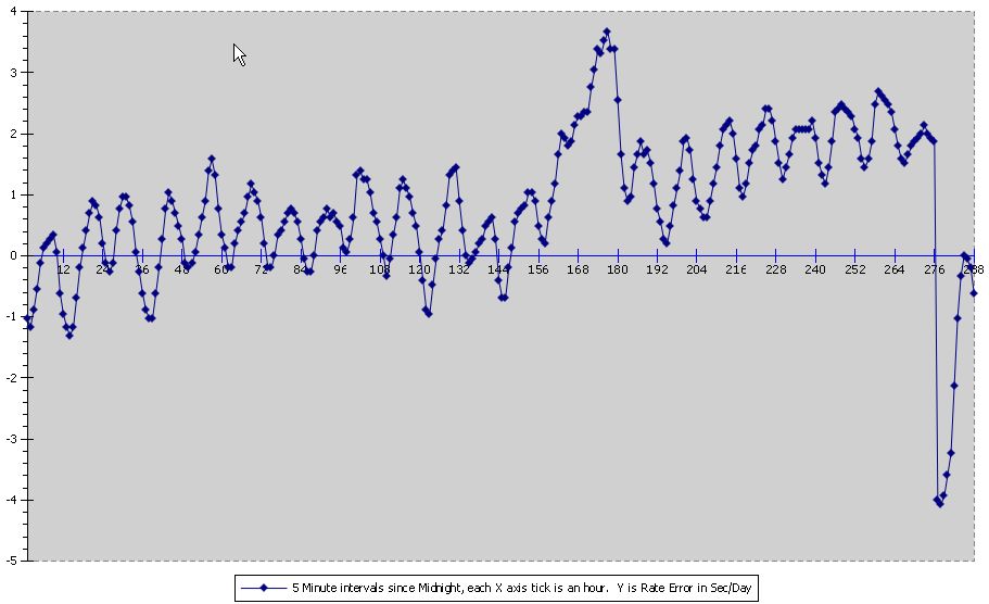
I've run this clock with the Watcher for a some time now and it seems reasonably stable, the rate rambles up to +/- 2 seconds per day. Not clear yet what the daily average will be since I'm still working on the clock. The pendulum isn't in final form (I'm still fiddling with temperature compensation) so this may be affecting stability. There is a 1+ second per day cyclical rate change superimposed where this variation occurs hourly and seems to be from a slight bind in the daisy mechanism; removing the daisy eliminates most of this cyclical variation. Here's an example Watcher chart; the big jump at 11pm is where I added an adjustment weight to the pendulum the day before.
In a way, the Clock Watcher provides more information than I wanted to know. The pendulum seems to be disturbed considerably by the large, once per minute, impulse: the impulse cycle is about 70ms shorter and the immediately following cycle is about 12ms longer than the average. Following cycles alternate being longer and shorter than the average much of the time between impulses. It acts as if there is a sub-harmonic superimposed on the pendulum's natural frequency, not an obvious operating mode. This is gleaned from observing the Watcher's display of raw data so perhaps it isn't an accurate conclusion and could be a problem in the Watcher software, although it didn't happen with my earlier clock which impulsed on each cycle.
Note: my Clock Watcher is cobbled together from parts and a micro-computer board that are not readily available so it isn't easily possible to make a copy. Bryan Mumford produces a commercial clock timer. There might be a software alternative...
Having read Dr. Woodward's "My Own Right Time", I tried to proceed along similar lines in construction, using John Wilding's book for basic information and measurements. This lead to several minor differences between my clock and John Wilding's interpretation of Dr. Woodward's clock. John Wilding has written a number of books on building traditional clocks using traditional techniques so Dr. Woodward's clock was a departure from his previous experience, as it would be for most. You can see this in the way he mounted stops for the counterbalances on sturdy arms. So my version differs from John Wilding's in minor details like this as well as the quite different maintaining work.
Lucite was used for the count wheel per Dr. Woodward's original clock. This made it easy to cut the wheel plus it allows adding a seconds indication very simply: numbers on the side of the count wheel. I used a spin indexer with a fly cutter in the mill to make this wheel; since the spin indexer only indexes by degrees, my first count wheel has teeth at 7 and 8 degrees alternately - ratchet wheels are less fussy than gears in this respect (but this does make it more sensitive to maximum pendulum amplitude). There is a caution in Wilding's book about friction if Lucite is used for the count wheel. I did run into a friction issue several months after installing the clock when it became unreliable. I had used 0.025 wire and partially counterbalanced the count wheel pawl to minimize friction; occasionally the friction wasn't enough to move the count wheel backwards to contact the backstop pawl. So I made the backstop pawl wire longer and bent it toward the count wheel so the brass section holding the backstop pawl is almost vertical. This reduced the friction of the backstop pawl enough that it ran reliably again. It is better to have the count pawl's weight/friction on the heavy side - when friction is slightly too low the clock can stop randomly (it can run for minutes to days between stops) and it takes a while to figure out what's causing it. I haven't seen any indication of excessive frictional losses from the Lucite count wheel, just this effect of relative friction between count and backstop pawls.
An observation on my first count wheel was that the teeth were deeper than necessary. Making the notches only about 25 thou deep with one notch full depth (60 thou, rounded at the bottom) makes adjusting the pawl to catch the deflector much easier. Originally this adjustment had little margin for error. The new wheel looks much different, of course, with just small triangular notches and one large notch. I made a special pin for my spin indexer to handle 1/2 degree increments so this wheel has 7.5 degree spacing between notches. The revised count wheel is shown at right with ink added near the deep notch to emphasize the details. Shown in place here. The original count wheel, with deep notches, is visible in this picture.
I press or friction fit most things in this clock. In particular, the arbors were knurled lightly as needed with a fine straight knurl so the 1/8" reamed collets fit but their position on the arbor could be adjusted; this was helpful in getting everything to line up nicely. Using Loctite would have made position adjustments far more difficult. Adjustments were necessary to accommodate my maintaining work - I didn't draw it first, just winged it as I went along. Loctite was used to secure the count pawl because setting the pickup of the deflector was touchy and it kept getting knocked out of kilter during testing; Loctite in this one spot made life easier.
The mill's DRO was used to drill the holes in the pin wheel; fairly fast, very accurate and no doubt about the result. Watching it work, I'm glad the wheel is accurately made because clearance with the escape in operation is not large.
0.031 music wire was used for the pins in the wheel and for wires on the counterbalanced parts. 0.025 music wire was used for the count and backstop pawls. 0.031 stainless safety wire was used for other wires where ease of forming was helpful; in particular, the stops for the escape and the deflector. These stops were mounted by drilling parallel #60=0.040 holes through the mounting pillars, then making a "staple" from safety wire with one side long to be formed as needed for the stop. These staples were pressed into the parallel holes where the slight mis-alignment inherent holds them firmly in place; the wire is bent as required for the stop. Note that the mounting pillars were first put in place and marked so the staple holes are approximately in line with the expected stop position; these stops are visible in this picture but are obvious only if you're looking for them. Adjusting these stops is done with finger pressure since this wire is fairly soft.
Pillars were made from recycled line printer shafts; I didn't use brass or cut the tapers specified --this makes it easy to install and remove them using a drill chuck as a grip.
The pillar for the pulley on the jockey weight side of the drive wheel is 0.2" longer and the pillar on the drive weight side is 0.1" shorter than called for in John Wilding's plans. This was done to reduce friction between the lines at the crossing point; not clear whether it is helpful but it seemed like a good idea at the time. I tried the line run so friction is increased and the clock stopped so this seems to help a bit.
The mill's DRO also simplified making the daisy wheel. I programmed the DRO for 22 bolt holes and set the diameter for the bottom of the V between petals, then drilled the even numbered 11 bolt holes with a #56=0.046 bit. I then set the diameter for the center of the petals and spotted the odd numbered 11 holes. These spots were used when scribing the petals prior to nibbling and then filing the daisy to shape. The pin wheel center and 4 holes were also spotted and drilled with the DRO's bolt circle function and their accurate location was helpful in fitting the cam and then final fitting of the daisy. (I have since gotten a jewelers saw which would have made things much easier.)
It's been more of a challenge to make this clock run well than I anticipated, partly because I'd like it to be somewhat temperature compensated. Initially it clearly wanted to run and when installed it ran well for quite a while... and then it stopped. I'm still learning but it's making more sense as time goes on. I made a number of changes to John Wilding's version but I don't think those changes have caused the issues I've run into. My initial changes were to eliminate fixing screws for wire parts and to minimize "clutter" from excess parts, mainly based on a different feel for how the clock should look. I've continued to fiddle with various aspects over time and added some minor refinements which seem to make it more reliable. In this section I'll cover some details that I think have improved the clock's ease of adjustment, reliability or time keeping. Plus some thoughts on how to adjust it. The adjustments interact so I may not have all the interactions covered... but I'm doing better than when I started ;-) . Two interacting systems form the oscillator: the count wheel and the hook+escapement; they connect via the deflector. I haven't adjusted the deflector other than its stop, i.e. the wires haven't been bent since construction. Update: added the deflector coil spring which was a MAJOR improvement.
My approach is to set the impulse pawl up carefully so it takes little movement of the deflector to hook a pin. The pin it hooks must be positioned so that once hooked it releases the escape, the impulse is delivered to the pendulum, and the pawl releases from the pin. The deflector's timing is set by it's relation to the count pawl as the pawl drops into the deep tooth - which is set by the lengths of the count and backstop pawls. To get this all adjusted I work back from the impulse pawl to the count pawl.
The impulse pawl (or hook as I often call it) is less critical to adjust if the tip is ground away so the tip is flattened on the outside of the curve. It should be positioned so its closest approach to a pin (as the pendulum swings) is about 5 thou. The pin wheel diameter could be slightly eccentric so look for the closest pin when setting this. Move it up or down on the pendulum rod or bend the pawl wire to set the clearance. Then set the deflector stop so the deflector clears the impulse pawl by 5-10 thou. With the pendulum at rest, set the escape so the tip of the hook is about mid-way between pins or up to one wire diameter to the right.
 The tip of the deflector wire, which will be caught by the count pawl at the deep tooth, should be nearly above the count wheel arbor and about one wire diameter below the wheel's outside diameter (assuming a wheel with shallow notches as described above). Bend the wire as necessary to position the tip appropriately. This completes setting up the escape+deflector so the escape will activate properly when the count pawl pulls the deflector's "trigger".
The hex nuts used to hold the clamping bracket for the pendulum spring were replaced with knurled brass nuts to make this easier to adjust. The gathering pawl was shaped differently to make its length easier to adjust - more on this below. The count wheel was replaced with one that has shallow notches rather than full depth teeth (covered above) except for one deep tooth. The backstop pawl was fit into its brass holder, secured by adding a slight bend - a crink - near the end to increase friction; this allows changing the length of the backstop pawl by sliding it in or out of its mounting hole.
There are three requirements to the count wheel setup so there are three adjustments, two of which interact. The simple, non-interacting adjustment is the angle of the count pawl section which rests on the count wheel -- this must be set so the wire clears the tip of the deflector wire when it is in the shallow teeth and must catch the deflector wire to trigger the escapement when in the deep tooth. The revised count wheel makes this adjustment easy because the wire drops considerably at the deep tooth.
The other two adjustments are the length of the count pawl and the position of the backstop pawl. To adjust the length of the count pawl the wire is bent at the bend points, keeping the straight sections straight. This allows adjusting the distance between the pivot and the straight section that contacts the count wheel.
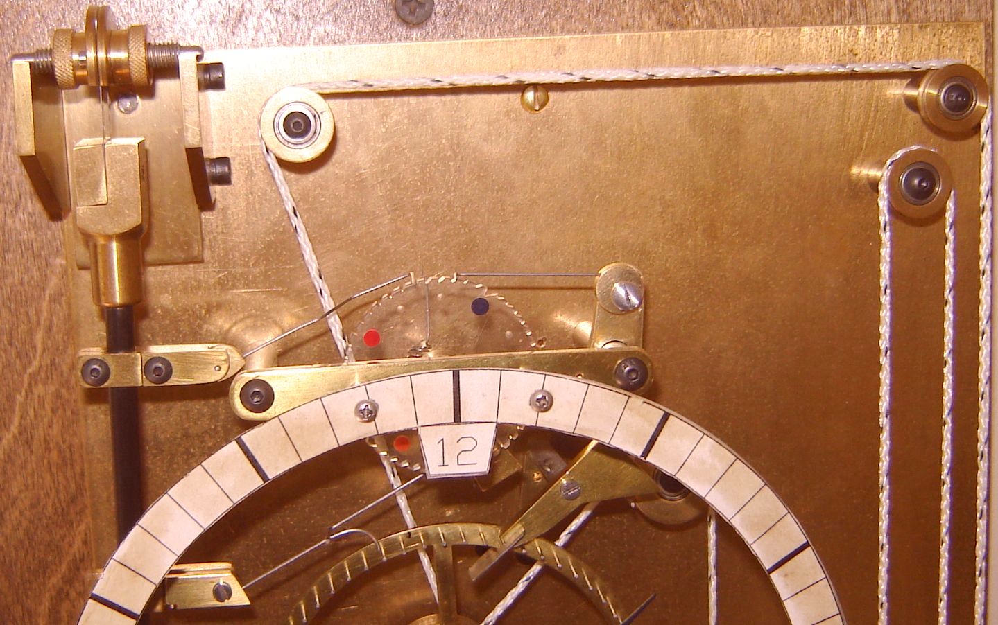 The backstop pawl is set so that the count pawl, with the pendulum at rest, is at the center of the slanted part on the deep tooth. The trick here is that the count pawl must also catch the deflector as it slides down the deep tooth and pulls the tooth toward the pendulum. This typically requires adjusting the length of the count pawl to set its position relative to the deflector wire, then adjusting the backstop pawl's position so the count pawl is at the middle of the deep tooth with the wheel against the backstop pawl. It takes some time and multiple iterations to get this right but it is key to reliable operation. The revised backstop support simplifies positioning the backstop pawl. When set properly, as the pendulum is moved slowly left the escape will trigger at about the same distance from center that the hook will release when the pendulum is moved slowly to the right. While the pendulum's horizontal position adjustment can be used to make minor tweaks to the position of the count pawl vs the center of the deep tooth, realize this also affects the hook position vs the pins. Click on the thumbnail at right to see some details.
Making the above adjustments can affect efficiency, causing the pendulum swing to increase. If this happens the drive weight must be decreased, either directly or (my choice) by increasing the jockey weight. This happened when I finally figured the above out - the pendulum rod would hit the case for a swing or two following an impulse. Adding a couple ounces to the jockey weight brought the swing back into the normal range.
When bending wire, some residual stress is left in the wire. A relatively mild force in the direction that would restore the wire's former shape can cause it to move part way back toward the former shape. When bending the count pawl to position it properly it is best to over bend slightly then press in the other direction moderately to get the desired shape and relieve the internal stresses.
Which brings up my concept of how this escape action works. When the count pawl triggers the escape, the action completes in about half a second - too fast for my eye to follow. In thinking about the action, it seems the deflector pushes the hook down and the hook then makes contact with a pin. At this point, friction between the pin and hook makes it difficult for the deflector to continue pushing the hook down. This increasing resistance of the deflector is passed to the count pawl; the pendulum resists this so the count pawl may flex slightly to allow the pendulum to complete its swing. This force from the count pawl curtails the pendulum swing slightly, affecting release of the escape. Of course, the hook is also slowing the pendulum simultaneously, so there's a lot going on in that half second. I added some coils to the upper deflector wire to limit the force it can transmit to the count pawl as well as limiting the force to the pendulum via the count pawl. The force required to move the count wheel is miniscule and the force to move the deflector is tiny too -- right up until the hook catches a pin...
 In December of 2013 I changed the deflector wire to include a coil spring as noted above, see the picture (click to enlarge). This makes setup much less fussy - possibly because the pendulum swing vs hook engage need not be set as precisely. The spring is from 0.020" wire, 10 turns spaced about one wire diameter apart. The start and stop points are approximately aligned so the bottom projection (1/4" long) is in line with the top projection. Upper projection length is 0.9" on my spring. A 0.024" drill was used to make a hole next to the original hole. The bottom spring projection's end was chamfered on fine carbide paper, then a fine copper wire (0.010") was inserted in the hole and the spring's bottom end was forced in. The copper wire provides enough friction to retain the spring and allows it to be rotated - the top and bottom projections don't align precisely so rotating allows fine adjustment of the tip's position (bend for coarse position). I made the spring slightly longer than needed and marked it with ink, then ground it to length. This required taking the clock's upper end apart a couple times to get the length within range to allow adjusting pickup by the count pawl via bending the pawl slightly. This spring in combination with the revised count wheel makes getting the clock to run much easier. I noted a groove worn in the deflector wire where it contacts the hook as well as wear on the top of the hook - this spring reduces the pressure applied considerably so further wear should be much reduced.
 In January 2014 I replaced the backstop pawl. The new backstop support is an interference fit on the pillar to allow adjusting the backstop position by simply rotating the support slightly around the pillar; this simplifies setup considerably. Note that the backstop is longer so it rotates through a smaller angle when moving between count wheel teeth. This design makes it easier to remove and replace the bridge because only one shaft need be manipulated rather than two. With this design the backstop pawl can be flipped over out of the way when removing the bridge, something that was awkward with the original design.
In the past this clock would run for months and then stop; I'd putter around trying various things and it would run again - but I was seldom certain what change got it going (other than the issue in August 2012 with graphite). I suspect that some of the adjustments outlined here were near their limits and would occasionally drift enough to cause the clock to stop. I won't be certain for a year or so but have noted that it now reliably starts after removal/replacement of the pendulum, something that used to sometimes require tinkering to get it going again.
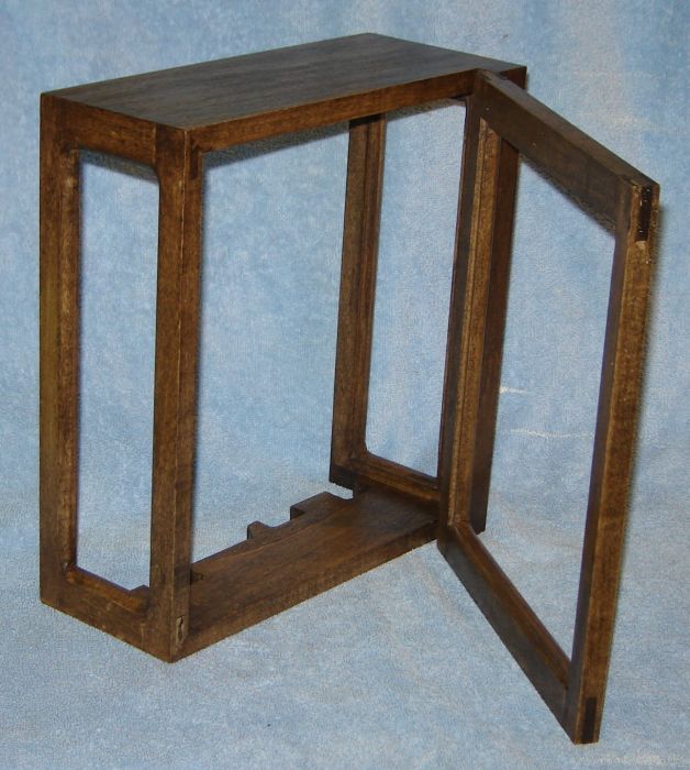
 I built a practice case for the gearless clock from inexpensive poplar to see if I could do it... my first cabinet making project. It took longer to build the case than the clock because I am low on that learning curve plus I had to make jigs and learn how to make joints with a table saw and router. A friend gave me some walnut for the actual case, once I recover from building this case.
My case design has a door to allow setting the time easily. Winding could be done by lifting the weight but I've found it easier to grip the string and use that to lift the weight - better control so the string doesn't get lifted off a pulley. The case bottom is split to allow the pendulum and strings through plus it allows easy removal of the case. There are two pins in the top of the case that engage the plywood back, so the case simply lifts off. The sides of the case have windows to allow viewing since I expect the works will be of interest to visitors. The clock is mounted on an outside wall (not the best situation) so I used spacers to hold it 1/8" from the wall to reduce heat transfer.
The gearless clock is a novelty clock so time keeping wasn't expected to be precise; the accuracy achieved is surprising. It was not reliable or particularly accurate initially. Changing the pendulum rod from fiberglass to carbon fiber was a big help. It also took a while to understand how to adjust this clock to run reliably. Once it ran reliably and temperature sensitivity was reduced it became much easier to isolate other issues. Changing the deflector to include a spring in the wire in combination with revising the backstop made it much easier to adjust. Once this was done the rate was more stable and I became suspicious of the maintaining work -- removing the sprag improved rate stability considerably. In February 2014 time was accurate within 2 seconds all month - however, it varies when there are large temperature swings outside which can cause a change of up to 2 seconds in one day. It needs a little more work on temperature compensation, I suspect I was lucky that the temperature swings balanced but it now exceeds the accuracy I expected. However, it took me over 3 years of intermittent tweaking to get to this - I hope the info here helps others achieve accurate, reliable operation more quickly than I did.
In building this clock, I set the pendulum horizontal position to the center of its adjustment range and adjusted the drive weight and escape timing so the hook moved the distance between two pins plus 1/2 this distance on either side of the two pins per Wilding's instruction. I set the deflector wire that the count pawl catches very close to directly above the count wheel shaft so it would move as far as possible when it drops into the deep tooth. The backstop pawl length was tweaked so the count pawl was at mid-tooth when the pendulum was still. There are 8 teeth between my count and backstop pawls vs 10 teeth in Wilding's picture. My clock ran fine with these default settings so things were left this way without experimenting with pendulum position and its effect on operation.
The gearless clock in its practice case was installed on 29 June 2010 and ran reasonably well but slowly accelerated with the rate increasing 1 or 2 seconds per day each week, where this effect was slowly getting smaller as weeks went by. On 20 September 2010 the clock stopped unexpectedly and refused to run for more than a few hours at a time. I puttered around with it improving minor items with the hope it would come back to life but the only thing that helped was adding 4 ounces to the drive weight.
Eventually I tried moving the pendulum horizontal position slightly and found this has a large effect on impulse efficiency as judged by pendulum swing. It took some back and forth between the pendulum position, escape timing, and deflector vs count pawl but I was able to get the clock running nicely again. I had set the drive weight with the original setup and now found I could increase or decrease the impulse delivered to the pendulum considerably by fiddling with these adjustments - not what I expected, I thought it was set for maximum efficiency initially. Escape timing also affects efficiency but is not as sensitive as pendulum position. I included a hole threaded 10-32 in the bottom of the drive and jockey weights to allow adding weight for testing and these were helpful in evaluating this issue. The end of the pendulum hook is brightly polished from contact with the pins in the wheel.
The clock is back to running with the original drive weight and I'm back to adjusting the rate. Setting the rate with little weights on top of the pendulum has turned out to be an excellent way to make small rate adjustments. With a little luck the slow rate acceleration I observed is gone thanks to this slightly different setup of the basic adjustments. Update: the rate seems much more stable although the clock stopped when the daisy locked up on 1 October 2010. It isn't convenient to attach the Watcher since mounting the clock in our living room so it takes a while to tweak the rate. I am currently chasing a second or so per day -- it may be much more accurate than I expected, assuming it doesn't start accelerating again ;-)
Week ending 17 October 2010: Clock gained 1 second this week. However, it seems to gain or lose up to a second per day - hard to say exactly. No sign of the earlier acceleration, at least so far.
March 2011: The yellow line began slipping through the drive pulley causing the weight to descend in a few hours. The yellow #18 drive line was replaced with a thicker #24 braided white line containing one black strand. This doesn't slip but winding makes me dizzy with all the black spots whizzing by :-) I also tried twisted (not braided) line but this spins the weights, winding the 3 lines into one. The hardware store people didn't know what the size numbers mean but #18 is, by eye, smaller than #24.
June 2011: Lengthened the backstop pawl to reduce its contact friction with the count wheel. This fixed an intermittent reliability problem. More info here. Rate is within 1 second per day.
June 2012: Temperature swings this summer made it obvious the pendulum was under-compensated for temperature. The original compensation was via aluminum tubing extending upward from a stop on the pendulum rod to the center of the pendulum. Length of the aluminum tube was a wild guess. The temperature excursions and resulting rate excursions allowed refining that guess and as luck would have it, the extra length of pendulum rod I left below the stop was enough to allow the extra length of aluminum tube to improve compensation. I added a bit over an inch of tube and tweaked the length (2.8 seconds per thou) to tune it so the clock ran slow by about 4 seconds per day, then added weights on the top of the pendulum to speed it up. This is a surprisingly precise way to adjust rate, much better than a rating nut since rate can be adjusted without stopping the clock and it allows very fine adjustments. I'd been chasing the rate around for over a year and it always seemed to be off by a second or two per day, probably because of the temperature sensitivity. Temperature has continued varying by up to 20F daily but the clock is within a second over the last 5 days which is better than I've managed previously - with luck it will remain stable over extended periods now.
August 2012: The clock stopped in a new way - the escape was against a pin, so it had not re-cocked itself. I hadn't seen this previously and didn't immediately deduce the cause so I restarted it and it ran for less than a day and stopped again. This time I noticed that the hook on the pendulum was sticking such that it didn't pop all the way up. I had used graphite on the shaft and this had packed itself into a lump in the pivot hole. I cleaned this out with a toothpick and normal running was restored. However, a couple days later the clock began gaining a minute randomly several times per day. This was traced to the deflector sticking, similar to the hook. Again, cleaning a lump of graphite out of the pivot hole restored operation. Best guess is that the exceptional humidity this August caused the graphite to clump up. While some graphite remains, it hasn't caused further problems. Oil isn't generally used in areas which pivot through small angles so I figured graphite would avoid the problem of oil drying up and preventing normal movement. Perhaps I used too much, it is difficult to control application of graphite from the squeeze bottle used to put it on automotive speedometer cables. Rate is back within a second per day.
December 2012: Replaced the fiberglass pendulum rod with a carbon fiber rod from the hobby shop. Carbon fiber's temperature coefficient can be set by adjusting the way the fibers are laid up so it was unclear whether this will be an improvement over the fiberglass rod. The aluminum tube used for temperature compensation helped a lot on daily rate variation but the change in temperature due to seasons causes a rate change of over 4 seconds per day. As part of this exercise I changed the hex nuts which set pendulum horizontal position to knurled brass nuts; makes it easier to adjust and looks better too. The sprag in the maintaining work has made marks on the large diameter section, one for each minute since it activates at each impulse.
January 2013: Made a new count wheel with smaller notches (described above), reduced the counter-balance weight on the pendulum pawl to make the CW movement due to friction more positive, and enlarged the holes for the backstop pawl's pivots to reduce friction. Coupled with adjusting the pendulum horizontal position this made the clock more efficient. I removed the extra drive weight added some time ago for testing but the pendulum swing was still too large, causing the rod to strike the case - so, I added 2 ounces to the jockey weight to get the swing angle back to what it was originally. The carbon fiber pendulum rod has improved temperature stability such that there is no measurable change over night when our setback thermostat reduces temperature. Rate seems more stable than it was, now < 1 second per day and more predictable than it had been previously. When the seasons change I'll get a better feel for temperature stability.
February 2013: The clock gained 2 seconds between 13 and 24 February, then between 24-26 February it lost 1 second (likely due to a warm spell). The rate seems more stable than it was with the fiberglass pendulum rod. Apparently even with the carbon fiber pendulum rod it has a positive temperature coefficient, so I'll remove the steel tip I put on the pendulum rod and pin it in the brass pendulum mounting block. Promotes real respect for John Harrison temperature compensating his clocks - I doubt I'd have the patience without the radio controlled clock to provide feedback.
March 2013: Removed the steel tip from the top of the pendulum rod and used a pin to capture the upper end of the carbon fiber rod in the brass piece. Shimmed the pendulum for this new setup so it runs about 1 second per day slow and added weights on top of the pendulum to set the rate more precisely. It is now easy to get the rate within 2 seconds per week which is in the range of variations due to atmospheric pressure. Of course, the dial and case remain to be completed but the works are about done, finally.
December 2013: The string began slipping again. Rather than replace it I rubbed a small amount of pitch from a white spruce tree along the length of string with the idea it would increase friction (like rosin). This dried in a day or so, is invisible and eliminated slippage. Don't know how long it will last, of course. While dealing with this I noted a small, slightly rusty looking area on the top of the hook where the deflector contacts. A groove is worn in the deflector at the contact point so I added a spring to the deflector.
January 2014: Revised the backstop pawl and its support to simplify setup.
March 2014: In mid January I noted the pendulum swing varied causing circular error. I tried removing the sprag since the maintaining work is activated at each impulse so any difference in how the sprag locked would affect the impulse. This reduced the rate variation considerably. I adjusted the pendulum shim and added weights on top of the pendulum to fine tune the rate; on 1 February the time was 2 seconds slow. I made no further changes during February and on February 28 the time was exact according to the radio clock. While the time varied during the month, it remained within 2 seconds of the radio clock throughout. It is affected by outside air temperature because room temperature varies at night when our setback thermostat allows temperature to drop as low as 55F (depending on outside temperature). Hard to say whether this stability is just luck but it is far and away the best the clock has done up to this time. I suspect temperature is not well compensated but need warmer weather to be certain.
Note: I found a problem with my La Crosse radio clock - fortunately, it has only a minor effect on the gearless clock's calibration, about 1/2 second per week.
August 2014: I set the clock in mid June and as of mid August it is 9 seconds fast, i.e. it gained about 1 second per week during this period. The weather has been cooler and more stable than usual this summer so the rate change between spring and summer was clear - the clock is over compensated for temperature so I need to remove some of the aluminum compensating tube supporting the pendulum.
October 2014: I set the clock in mid June and as of mid October it was 1 minute and 4 seconds fast. A warm spell in late August and early September seemed to cause this, again the over compensation of temperature. The heat is on occasionally now so rate varies randomly again, as it did last winter.
June 2015: Over the winter I purchased (eBay) and installed a chapter ring. The chapter ring is supported by springs so bumping it accidentally won't damage it or the clock; it is easily removed by loosening one thumbscrew. The clock stopped mysteriously and this was traced to a spot on the drive string that had too much pitch on it causing it to stick as it passed the drive pulley. Bending the line back and forth at this spot a few times cured the problem (the dried pitch came out as powder). While the furnace was on the clock ran slow by varying amounts, 10 to 15 seconds per week; a small weight on top of the pendulum removed much of this. Now that summer is starting the weight has been removed and it is 2 to 4 seconds slow per week, so it remains slightly sensitive to temperature (mainly due to lack of ambition on my part).
February 2017: The string began slipping again, requiring winding every 3 days. A little resin rubbed on the string fixed this, just like in December 2013. So it looks like this is needed every 3 years or so.
March 2017: The clock began losing up to 5 minutes per day. I noted that the count wheel didn't always move backwards to contact the backstop pawl and that this would sometimes cause it to miss advancing by a second. This apparently happened many times per day. I added a tiny weight to the count pawl to increase its friction with the count wheel to overcome the miniscule friction of the backstop pawl resting on the count wheel to cure the problem. It gained 1 second over the following week so it's back to normal.
January 2018: The clock stopped - which wasn't really a surprise. I had noted in December that the escapement sound had changed such that the release didn't make a positive click although the click as it locked was normal. It seems I had used graphite on the escape pivot and it apparently clumped up similar to the August 2012 incident with the hook pivot. Cleaning the graphite off of things restored normal operation.
February 2019: The string began slipping again so I rubbed a little resin on it to correct the problem. Apparently, winding this clock - done by gripping the string to lift the drive weight - slowly removes the resin so this will be needed every couple years. Currently gaining about 4 seconds per week.
April 2021: The clock stopped - cleaned and oiled escape pivot and count wheel pivots.
July 2021: The string began slipping again so rubbed rosin on string. As noted earlier, this is necessary every couple years.
If you have a comment on my site or its contents, click here scroll down and click again.
This page was last modified