* GadgetBuilder.com *
Last Modified:
There are several mods to the mini-lathe which are minor, quick to do and help some facet of its operation, reliability or maintenance. These items aren't worth adding a new page for each but they do address details that may be worthwhile, depending on the uses to which the lathe is put.
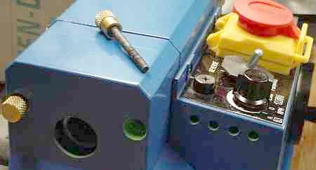
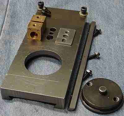
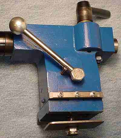
The picture at the top of this page is interesting because it shows four minor mods in one small area. First, the large hole in line with the spindle was made a bit larger to accommodate the shaft of the handwheel; this allows using the handwheel without removing the cover as I had to do originally. I use the wheel frequently so this saves a bit of fuss installing it; I prefer the wheel to a crank because the grip is always in the same place. The Dremel made short work of enlarging the hole.
The hex bolts which retain the end cover are removed frequently to change gears for threading. To simplify this I made small brass caps for these bolts, knurled them, and pressed them onto the heads(suggested by Engineman). The holes in the cover were drilled out a bit to pass the slightly increased diameter.
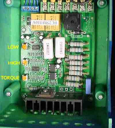
Moving further to the right, holes were drilled in the side of the cover which holds the speed controller. In addition, the bottom of this cover has a number of holes added to allow air in with the idea that heat generated by the board would cause circulation from the bottom holes through the top holes. Hard to say if it helps but it doesn't hurt and is easy to do. In addition, the holes in the bottom provide an outlet for small chips which enter via the leadscrew - not foolproof but I haven't had a problem so far.
The last item in this picture is the flat rubber shield on the Fwd/Rev switch. Several owners have developed serious electrical problems from chips entering around the handle of this switch and falling through into its contacts. This little scrap of rubber eliminates the problem -- Radio Shack sells more elegant covers but this works well and cost nil.
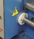
Another el cheapo mod is a shield to minimize chips entering the control box through the opening for the lead screw. I drilled a hole in a milk bottle top (I'm looking for a blue replacement) a bit smaller than the leadscrew and added some short radial slits. When the carriage was off for other reasons I simply pushed the shield along the leadscrew. This works especially well for "skimming" cuts ;-)
(Added May 2004)
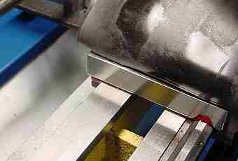
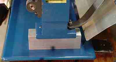
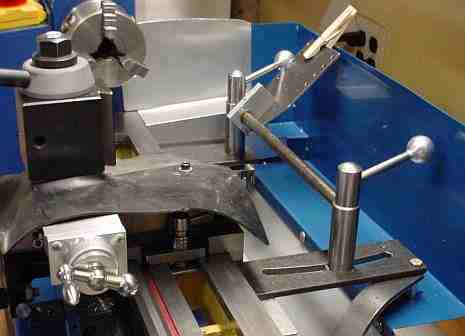
A way wiper is another quick mod once you find a bit of aluminum angle. A piece of felt is trapped under the angle, held in place with bolts in the holes intended for the traveling steady. My rubber way protector (shown flipped up in this picture) is held by the same bolts. Apply generous amounts of Vactra to the ways and it will be picked up by the felt and automatically redeposited as the carriage is moved back and forth. Use a chip brush to sweep chips off of the felt wipers occasionally. A similar thing could be done on the other side of the carriage but I haven't because relatively few chips make it to that side.
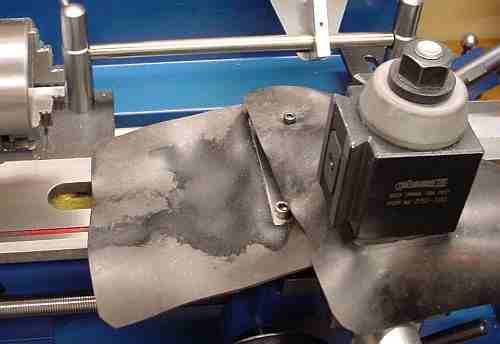
Way protectors help to keep chips off the ways and also off the carriage leadscrew and out of the apron gears - I have never fitted protection for either of these because the way protectors have it covered (so to speak). Way protectors are also easier to make than the protectors most owners fit so this appealed to my lazy nature. The upper protector is anchored by one of the screws used to hold the part that drives the cross slide when making tapers (experience has shown this isn't necessary). A fringe benefit of way protectors is that they simplify chip cleanup. Cutting oil soaks into the soft rubber I used so the protector needed replacing after 2.5 years. The replacement is 1/16" Nitrile from Enco; it seems much less sensitive to oil than the original rubber.
The cross slide on my mini lathe had more backlash than desired, typically 4 thousandths. This would re-appear within a week or so after adjusting the brass nut for 0.001 backlash and would increase slowly thereafter. The brass nut seemed to wear rapidly following adjustment making backlash adjustment an exercise in futility. I smoothed the leadscrew threads with 1500 grit paper and crocus cloth but this didn't solve the problem. The cross slide ball bearing mod only made the backlash more obvious.
Will Hamlyn's split nut mod simplifies backlash adjustment and will, I hope, also minimize wear to the brass nut so backlash will not re-appear so quickly. My notion is that the original adjustment scheme of tipping the nut concentrates the wear areas at the top of the nut on one end and at the bottom of the nut on the other end; Will's mod spreads the wear over the whole circumference and uses all the threads so it should wear much more slowly (it says right here ;-). This mod is larger than most of my mini-mods - it took a bit over 2 hours to complete.
The hole for one of the brass nut retention screws was lengthened by 0.050 -- this was a two step procedure, first the pocket for the bolt head, then the hole for the bolt. I slotted the hole toward the compound but in retrospect it would be better to slot the other hole - the handle of the Allen wrench is trapped between the compound and the screwdriver used to lever the nut apart in my setup.
The holes for the pins were drilled and then the nut was cut with a 0.012 slitting saw; this took two passes, one from each side because of the small blade diameter.
I used finishing nails for the pins. These were 0.070 diameter so I cut the pointed end off, then reduced the diameter a couple of thou with a file (the cross slide was out of commission, of course) for most of the length which was to go into the brass nut. This produced a free fit in the drilled holes; I tapped the pins in place so the large section wedged in the drilled hole and then milled the protruding part of the nails off flush - simple and quick, works well.
I measured the space under the original brass nut prior to removing it. A spacer of aluminum was whittled to shape with drill press and files, including a larger than normal hole in the center and a slot on one side to match the slot in the cross slide.
The split nut is easy to adjust by inserting a small screwdriver in the center hole where the height adjustment for the brass nut was previously. Only the bolt in the slot need be loosened to adjust backlash. The result is backlash of 0.001, about what it was previously immediately following adjustment. I'll update this with info on how long it takes for the backlash to re-appear when I have used it for a while. (After a week of use the backlash is back, similar to before the mod. Perhaps it needs to wear in at first? Readjusted, and the backlash came back. Now, I can't get the backlash below 5 thou -- so, I will try splitting the old nut lengthwise shortly.)
An alternate approach occurred to me as I was doing this mod. The nut could be split lengthwise on the bottom only, then the bottom could be squeezed together (VERY slightly) in a vise. This should close the hole a bit and the springiness should eliminate backlash for a long time by slowly closing as wear occurs - this should work on the minilathe because the leadscrew threads are 60 degree rather than Acme. Engineman mentioned that his Taig uses this scheme and never needs adjustment.
Several owners have tried the longitudinal slit and results vary considerably because it isn't an easily controlled process. About half find the mod works well for them while others find the nut cracks (as my nut did) or the backlash returns fairly quickly.
I expect the nuts vary some in their properties plus the slit width differs between implementors so the amount of squeeze applied, as limited by the slit width, varies. If you get it right, the springiness of the metal compensates for wear over an extended period (assuming good lubrication). If too much compression is attempted then the nut cracks. If too little compression then with minimal wear the backlash returns. Heating the nut would anneal it - it wouldn't crack but loses springiness so it can't take up much wear before backlash returns.
A different concept would be to make a replacement nut blank from steel but bore it out and press in a round nut made from plastic - HDPE, Nylon or Delrin might be worth trying (with a little graphite for lube). I made a lead nut for the Brooks grinder from Delrin this way and it has little to no backlash - but it hasn't had the use the 7x12's CS nut gets either.
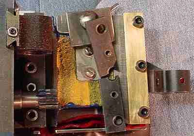
A common mini lathe failure occurs when the carriage slide plate cracks, typically because of over-enthusiastic adjustment (guilty as charged). It seemed like a quick fix so I made a replacement rear slide plate from brass, copying the hole positions with a transfer punch. A cardboard shim 0.023" was about right and things were going along great, taking only about an hour. Since the leadscrew bearing block was off I added an oil hole, a #17 drill nearly through, with a #56 to finish; a bit of felt in the large part of the hole allows oil through and keeps chips out.
On reassembly, the drag from the new slide plate was greater than the old slide plate causing the carriage to swivel slightly when changing directions. I tried to adjust the front slide plate and found it impossible to prevent the swiveling unless the front slide plate was so tight it locked the carriage. The carriage was removed and the "V" in the carriage was examined by inking it and sliding it back and forth on the prism and ways. Contact wasn't good unless considerable downward force was used. I noted that the smooth contact area in the "V" had visible ridges corresponding to the top of the prism; these ridges are easily detected with one's fingernail too. My guess is that the carriage doesn't make good contact with the sides of the prism because of these ridges.
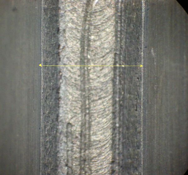
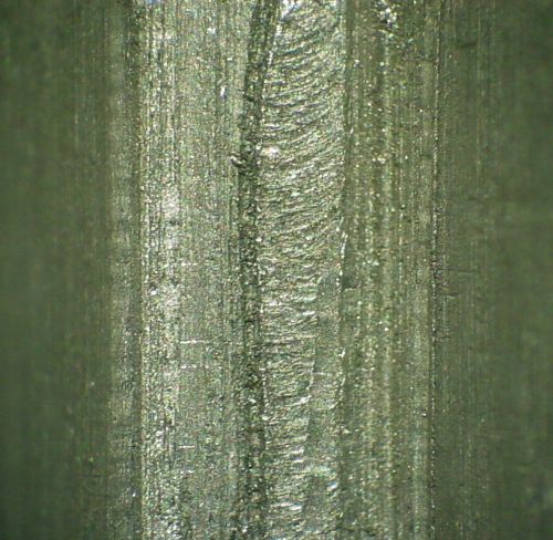
I considered running a 13/16" end mill along the "V", just deep enough to take the two ridges out in one pass -- one of the difficulties with owning a mill is that every problem that comes along looks like it can be fixed with a little milling :-). Instead, I made a tool by end drill/tap a piece of 1/4" rod, then used a 6-32 screw to attach a TPEG 322 carbide insert to the end. This was used as a rake-like scraper to remove the majority of the ridge - it was only about 3 thou - and then a fine file was used to tidy up; cast iron is soft and easy to work by hand for small things like this. The existing contact areas were not touched while removing the ridges. Here are Before and After pictures looking straight down into the central part of the "V".
In addition to removing the ridges in the "V" I replaced my cardboard shim with two 0.013 aluminum shims and also fitted aluminum shims in place of the adjusting screws for the front carriage slide plate. This eliminated the swiveling as well as a slight loosness in the carriage, the original goal. (The rightmost 3" or so of the bed was a couple of thou thicker than the rest so I filed the bottom where the slide plates contact to even things out -- accuracy wasn't critical since the carriage only passes by here while being removed.)
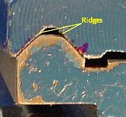 I then checked the "V" in the tailstock where I found and removed similar but smaller ridges. This seems to greatly reduce the ongoing problem I have had with repeatability of the tailstock position, kind of a fringe benefit of fixing the carriage slide plate. Ridges run the length of the "V" at the points shown, corresponding to the top of the prism.
The ridges in the "V" may be from wear (my machine is about 2 years old now) or they may have occurred during manufacture, hard to say. The effects produced by the ridges are small so it is easy to overlook them in use -- I kept running into the tailstock repeatability problem but didn't know what might cause it until I tripped over these ridges. Since it is easy to determine whether the ridges are present by simply looking (and/or feeling with a fingernail) once you know where to look, it would be reasonable for readers to check for this. As noted above, the fix is quick and easy.
Another common problem is varying bed thickness along the ways which can make for a poor fit of the slide plates. The rear of the bed is more critical and easy to measure with a micrometer. I measured every 2 inches and wrote the thickness on the top of the bed with Sharpie. I used a copy of Rick Kruger's filing jig (made from white HDPE) to correct the thickness within 3 tenths.
I wish I had replaced the carriage slide plate adjusting screws with shims earlier than I did. This was very simple to do and had I done it initially I wouldn't have broken the slide plate and had to make a new one. I had in mind making tapered carriage slide plates to allow adjustment but shims are so easy and work so well that now it doesn't seem worth the effort.
The handwheel on the apron had poor feel due to backlash in the gearing, particularly noticeable when changing directions. I made an eccentric brass bushing, 1/2" diameter with a 1cm hole offset by 20 thou in the 3 jaw with a shim. The apron was drilled and reamed 1/2", one end of the bushing was reduced slightly with a file so it would start into the hole; the bushing was inserted slightly and tried with different orientations to find the maximum engagement of the gears without binding, then the bush was tapped home with a mallet. This minimized the backlash from this source. The apron gears are well made and run true so there is no change in friction vs rotation.
The rack was removed and the mounting holes were drilled out by 15 thou as were the counterbores. The rack was re-fitted and a shim was fitted above the rack at several places to lower the rack slightly, increasing engagement with the apron drive gear. In combination with the eccentric bushing this reduced the backlash by about 2/3.
A thin washer was fitted between the handwheel and the apron to minimize endplay, further improving "feel" of the handwheel.
I found my lathe's tailstock offset measurement was much more repeatable after removing the ridges from the "V" so I added a gadget to aid centering the tailstock horizontal position more easily. It is just a 1/4" square bar across the back with 6-32 screws to hold the bar to the tailstock. The center screw is into the base while the other two are into the movable part. My tailstock is fairly close to centered when the top and bottom are aligned. I aligned it as best I could without the bar and ran a file across at the level where I put the bar -- this leveled the thick paint without removing it completely. Then, I put the bar in place.
The idea is that the outer two bar screws are tightened fully. The tailstock locking screws are loosened and the center screw is used to pull the top of the tailstock up against the bar. If it goes too far, the center bar screw is loosened and a shim is inserted, then the screw is re-tightened and the alignment re-checked. If it doesn't go far enough, shims are inserted near the outer bar screws. Once all is well, the regular locking screws are tightened. This approach is simple and seems to work well, at least I quickly got the horizontal error under 1 thou, something which took a lot of fiddling previously. The horizontal setting on my tailstock seemed to drift randomly; my hope is that this mod will also eliminate this drift.
Realize, I never offset my tailstock deliberately -- it has always been so difficult to get it accurately aligned that I avoided moving it except under duress. The taper fixture eliminates the main reason for deliberate offsetting, anyway. If you offset your tailstock deliberately then this mod may be helpful in getting it back to center quickly, although you'll have to loosen or remove the bar to offset.
As time goes on I add more and more shims to my lathe, hard to say where or when it will end. Here, I went to the extreme of adding a place to put the shim rather than shimming an existing part. Simple and cheap, shims allow improving the lathe without making permanent changes which might not go well.
(Added October 2005)
The riser under my lathe wasn't quite enough for comfort so I used a 2x4 between the riser and the rubber feet. This worked OK but wasn't very stable when parting with a hacksaw (sometimes the best option)because the lathe feet are less than 3" apart. In addition, it was always difficult to clean under the lathe because of the minimal clearance. I found a couple of short pieces of 1.5 " square aluminum tube (1/4" wall) at the dump, same as the 2x4's thickness. By adding this between the lathe and the chip tray I got the desired height increase and improved access for cleaning.
To improve stability I added a 10x2.25x0.187 piece of flat steel (another treasure from the metal recycling pile at Newtown's dump) below the chip tray on each end and moved the feet as far apart as this would allow. This was positioned so that the front feet are out of sight under the tray while the back feet are clearly visible in the picture. This improved stability much more than expected, well worth the effort even without the height increase from the other part of the mod.
I purchased M6.1x60 bolts to accommodate the additional 1.5". This wasn't done smoothly - I checked the drawing in the manual to find the size which was given as M5 so I purchased the wrong bolts initially. If you decide to do something similar, look at the machine - not the manual. After the fact I looked at the manual to verify that it was indeed wrong and noticed a couple of other oddities: the manual shows an extension similar to mine below the tray plus there are rubber pads shown between the lathe and the tray -- neither of these were included on my machine from the factory.
(Added April 2011)
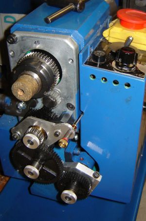
I do a fair amount of threading so gear swapping is common. This takes some time and is made more awkward by the use of two different size socket head bolts to retain the gears. These bolts don't need to be very tight so I pressed knurled knobs made from aluminum onto these bolts. No more fumbling around with Allen wrenches when changing gears!
(Added September 2008)
Click to enlarge

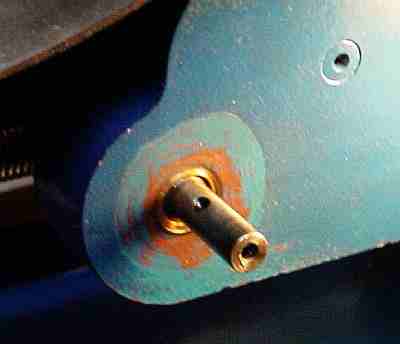
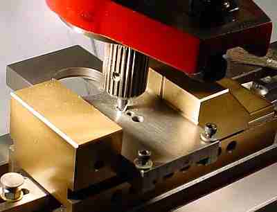
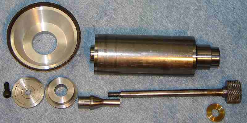
A "pot chuck" is a simple way of chucking thin work reasonably accurately, about as accurately as a collet if your 3 jaw chuck is repeatable. This example repeats within about a thou. This one was made specifically to hold the two work pieces shown, where either may be held from either side -- the opening in the pot chuck will pass the smaller section on each piece. These are parts for the Brooks wheel adapters, as shown here with the spindle. This scheme works much like a collet pot chuck but is actually a very short split sleeve with alignment shoulders. More about pot chucks.
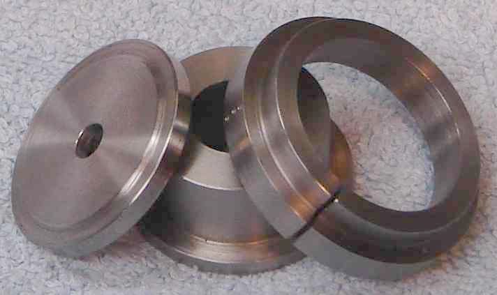 This picture shows the back of the pot chuck. It was made from a short piece of scrap by turning the OD to 1.875" and the smaller diameter to 1.62". The chuck-to-be was reversed and held by the 1.62" section (it is 0.200" wide). It was faced to be 0.445" thick (arbitrary) and the center was bored out to 1.29" -- this allows the 1.25" section of the work items to pass easily. The larger diameter was bored 1.580" to a depth of 0.117"; the short work items are 0.125" thick so they are slightly proud of this to allow facing them. Before removing the chuck-to-be from the 3 jaw it was witness marked at the center of jaw 3 with 3 center pops, as seen in the picture. It was also marked mid way between the chuck's jaws, then cut with a slitting saw at this mark and the edges of the slit cleaned up with a needle file.
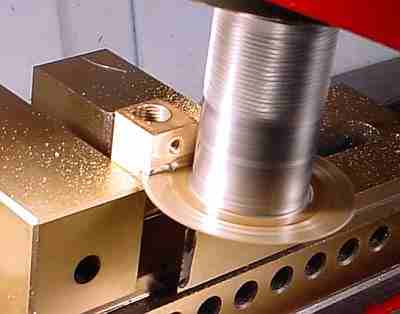
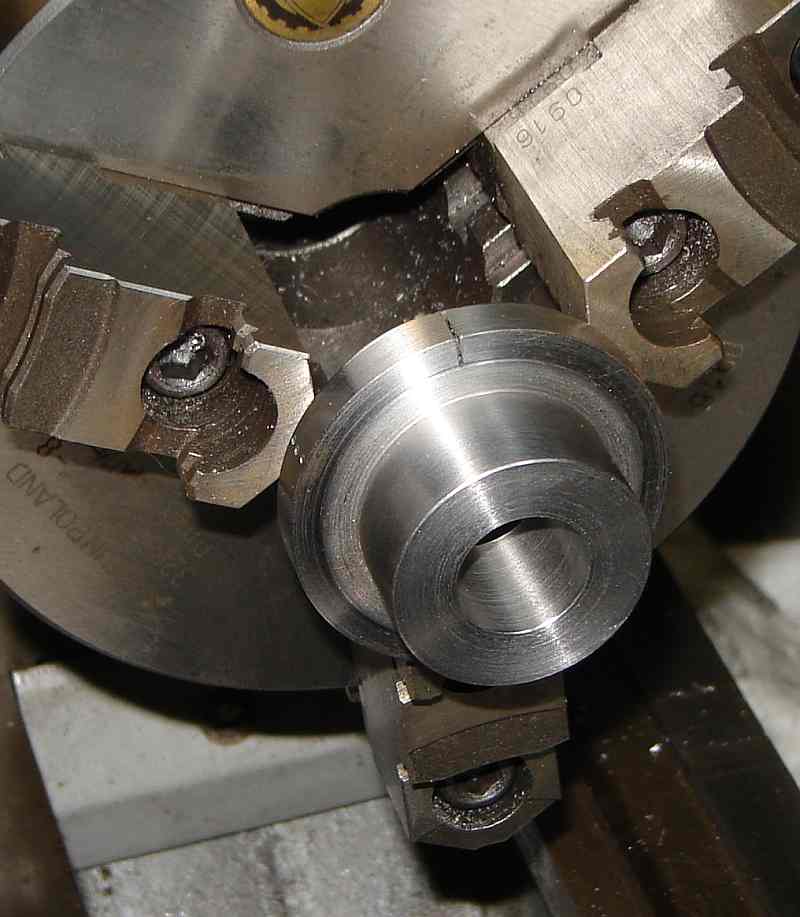 Placing the completed pot chuck in the 3 jaw with the witness marks centered at jaw 3 allows chucking the parts shown with a runout less than 1 thou - not bad for a work holder made from scrap. The picture shows how the slit is positioned between the jaws; note the witness mark centered on the jaw. The part shown can be reversed in the pot chuck also, allowing all surfaces but the 1/8" wide OD ring to be machined in this chuck.
 Pot chucks are a simple, quick, accurate, and inexpensive way of chucking thin (or not so thin) items. The pot chuck for 1/8" thick items illustrated here is only an example -- much thinner items can be held reliably with the same technique. Lots of possibilities for variations on this theme. At left are 5 pot chucks I've made for various projects; when possible make them for standard material sizes to improve chances of being able to re-use for another project.
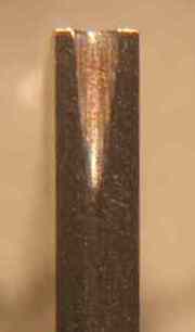
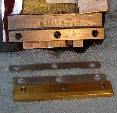
The most common problem with a gib is that it is bent slightly. This causes it to bind while it is still not really close to the dovetail. To fix this, remove the gib and decide which direction and where (over its length) it is bent. Grip a short piece of 1/4" or larger round material in the drill press chuck. Place the crooked gib on the drill press table with the highest point on the gib facing upward directly under the chuck. Put a penny under the gib some distance from the high point, then use the drill press like an arbor press to reduce the bend. The penny under the gib limits the amount of reverse bend so you won't over-correct or break the gib. Go easy at first and check progress. Increase pressure as needed but realize the drill press wasn't meant for this so be reasonable about the force. If necessary, put another penny on the other side of the bowed area and press again. A little experimenting with this should allow you to get the gib almost straight. It's worth fiddling around with this to get it as straight as you can because any remaining bend must be removed by grinding - a slow process in comparison.
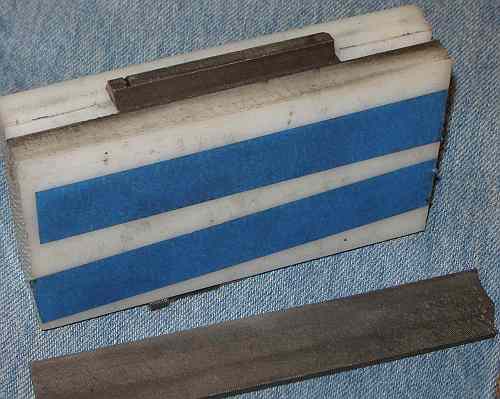
To grind the gib flat, use a strip of wood - or preferably Melamine - as a holder, built as follows. Cut the heads off 5 finishing nails -- parting on the lathe or a hacksaw works for this. Lay the gib on the holder and put 2 nails separated on one side (near the ends of the gib) and one nail on the other side mid-way between the first two nails; this nail should be tight up against the gib so friction holds the gib in place when the holder is inverted. 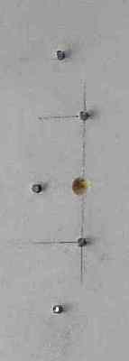 Add a nail at each end to trap the gib in the holder. The top of the nails must be below the gib strip so the gib can touch the grinding surface without interference from the nails. I used melamine for the holder and drilled the holes for the nails on the drill press, being careful to get the one nail that creates the holding friction positioned correctly. If it isn't just right, remove it and try again a 1/4" away. (The drill divot shown on my jig makes it easier to pop the gib out of the holder.)
Using carbide paper face up on a surface plate or other very flat surface, rub the sliding surface of the gib (the side without the pips for the adjusting screws) lengthways on the paper using the holder to ensure the strip is held flat and has even pressure. Start with 220 grit paper to get it flat as judged by eye. You can pop the gib out of the holder with the tip of a knife for inspection, then replace it for further work. Polishing with finer paper is good but not necessary; once it is flat, I typically go through 400 and 600. (No need to work on the opposite side of the gib unless the pips are defective.)
When you replace the gib into the lathe ensure it goes back the same way it came out so the adjusting screws contact their pips properly. When you adjust a properly flat gib it may be fairly touchy - very little rotation of the adjusting screws between free movement and locked.
If it comes to that, it is possible to make a new gib with a file. Get a short piece of 2X4 you can clamp in your vise. Cut a slot at the proper angle - you can use the original strip as a guide to get the angle about right. Use a piece of brass or steel of approximately the right size, put it into the slot - adjust the slot as needed to get it so the strip is supported level (hot glue and bits of metal embedded in it may help) end to end and then file the angle on the side, invert (being careful to get it oriented correctly) and file the angle on the other side. File to get the gib width correct, finish as above, then add the pips. It will take a while but a good sharp file can do a lot - a shaper is the easiest way to do this and a mill works too but is a bit more difficult to set up. Still, in a pinch a file will do it. If you decide to make a new gib, try to fit it to the opening as closely as possible (the original usually isn't a great fit).
Parting can be difficult on these little 7X12 machines, especially at the beginning when you're just getting used to the machine. And I still occasionally have trouble after 5 years. There's a laundry list of things to check while getting it to part nicely. One thing is critical: if the blade hogs in and stalls the spindle, shut the power down quickly to avoid damage to the electronics.
First, it's harder to part larger items because the chips have a harder time getting out of the deep slot. Practice on a 1/2" diameter (or less) piece first, removing thin slices just to get the hang of it. Parting should be done as close to the chuck as possible, where the chuck jaws miss the tool holder by 1/16" or so.
A 1/16" wide blade is a good size for these little machines; a 3/32" will work but may be more difficult to use. You need a good, solid holder for the blade or it will chatter. Lapping the cross slide and the compound is helpful; even if you don't get a perfect fit it will help. The gibs on both need to be adjusted properly to be firm but allow free movement. Sometimes the gibs need to be straightened and then ground to get them right - much easier to adjust them once they're straight and flat.
The parting tool should stick out from the holder only as far as necessary, again for rigidity. The blade must be sharp, of course, with proper relief. The compound should be parallel to the ways and backed off so the blade is over the cross slide. If the tool is beyond the edge of the cross slide toward the chuck then chatter is often a problem (leverage from the tool being hung out beyond the CS allows the cutting forces to visibly lift the gib side of the CS).
The tool should be slightly (1% of cutting diameter) above center. If it is a little low it will tend to hog in and/or chatter. If it is too high it will require more pressure to cut or it may not cut at all. The blade must be exactly perpendicular to the machine axis or the blade will rub on the sides. ( I set this with a parallel between the face of the chuck and the side of the parting blade.) Use plenty of cutting oil (WD40 for aluminum) while parting or friction of the sides of the blade on the work can be a problem, made worse by chips in the slot. On deep cuts it is helpful to back out and move over about half the width of the blade and come in again to widen the slot so chips don't bind things up; then alternate sides within the cut to keep the width open (although it will slowly narrow anyway due to blade flex).
 The parting tool needs a little side relief and the T shaped blades help here although you may need a shim to keep the blade vertical on some toolholders. The front relief should typically be 5° to 7° -- more than this and the tip can chip easily, less and it may rub. A small "V" in the top of the parting blade helps by causing the chip to be narrower so it can exit the slot more easily. When resharpening, a burr often forms on the top edge - it is important to clean up the burr in this little "V"(I fold some fine carbide paper and use that to remove this burr). The "V" causes the swarf to be very fragile so it often breaks up into small chips, further easing exit from the slot.
Sometimes chatter is caused by feeding too slowly. This is something you develop a feel for by practicing. There is a fine line between feeding too slowly and getting chatter or feeding too fast and having it hog in and stall or break the tool (I've done both). And, the particular material you're parting can make a big difference - some material is just difficult. Sometimes changing the speed is helpful... but don't run too fast or you could break something if it hogs in. Slower often reduces chatter but too slow isn't good either. When parting threatens a hog in, raise the blade a couple thou and conversely if it requires higher than normal force to cut, lower the blade slightly (assuming a QCTP). As usual, it's trial and error and developing a feel for the machine and material. When chatter is a problem try raising the bit a few thou to see if it helps; the bit should be about 1% of cutting diameter above center to minimize chatter - this means on large diameter work it should be several thou above center but the height may need to be lowered as the diameter decreases - increasing feed pressure lets you know when to lower. The idea of having the tip slightly high is the bit will rub and prevent digging in if you try to feed too fast plus this contact will reduce chatter - that's why increased feed often reduces chatter (assuming your setup is correct).
As you can see from the above (and I may have forgotten something) there are a lot of variables that can affect the parting operation. Initially, some of the setup things (like lapping dovetails, flattening the gibs, and fitting the carriage) may need to be done before you can figure out which of the other possible problems is occurring. It's a matter of trial and error and experimenting, aided by knowing the above listed items need to be considered.
The 3 jaw chuck supplied with a minilathe is generally surprisingly good - I've been using mine for over 16 years and it has served me well. Below are some observations based on using this chuck over the years.
Chucks have variables that affect runout and repeatability more than one might expect and one often reads about grinding the jaws to improve operation. Grinding the jaws is a one way street - you can't put the metal back - plus, it is trickier than it first appears. It may be better to consider some other measures before grinding the jaws.
The first thing to do is dismantle the chuck, clean it and de-burr it - remove any rough edges that might interfere with operation. If the chuck has seen little use this may improve things considerably. Lube with a small amount of oil - chucks are noted for slinging excess oil on the operator and elsewhere. Grease is not a good choice in areas where chips may migrate but I use a dab of grease in a couple spots inside. Cleanliness and no dings are required for the spindle and chuck mating surfaces, of course.
Verify that the registration shoulder on the spindle fits the chuck well; my chuck's registration shoulder was a loose fit so the chuck registered differently, with differing runout, each time it was mounted (see Bump-Tru below).
A short hardened and ground test pin is useful when evaluating a chuck. A 1/4" drill blank or a shaft from a dead VCR's head motor (free) work well. Each time an item is gripped in a chuck it is held at a slight angle to the chuck jaws -- and this varies with each closure. The hardened pin helps reduce this and twisting it slightly as the chuck is tightened also helps. Clean, burr free jaws are assumed. Measure runout close to the jaws to minimize the effect from gripping angle which can easily be larger than the actual runout. (Gripping angle can be a problem on longer work but it can be minimized by gripping lightly, tapping the far end to true it, then fully tightening the chuck; verify that the work didn't move due to tightening and repeat if necessary.)
Try mounting the chuck on the spindle in all 3 possible orientations (leave the test pin in the chuck) - occasionally, one will work better than the others - if so, mark the chuck so it will always be installed in the favored orientation.
Then, try moving the jaws into the other slots (the order of the jaws must be preserved but try jaw 1 in slots 2 and then 3). Occasionally, this will reduce runout. If so, mark the slot where jaw#1 produces minimum runout with a punch mark. Clearly, you must remove the test pin so this introduces another variable - you will need to try closing the chuck several times for each trial position and average the results.
Then, if you check, you'll likely find that one of the holes used to close the jaws works better than the others - I put paint in the favored hole so I can use it when minimum runout matters. To locate the favored hole, close the chuck on your hardened test pin and record the runout; do this 10 times for each hole. If it works like my chuck, one hole will have less runout and there will be less variation in that runout.
If runout is still an issue and the chuck jaws aren't worn or damaged then here's a different approach to reducing runout: Bump-Tru
Bump-Tru requires you to re-true the chuck (by bumping with a mallet) each time you mount it, which you may find unacceptable - depending how often you swap chucks. However, self centering chucks often have different runout when gripping different diameters. Bump-Tru is generally close enough for most work when trued using a small hardened pin (0.250 or so). When you grip larger work you can re-true on the work itself when that would be helpful.
You'll be removing metal to implement Bump-Tru so this is also a one way street - not something to try if you're not sure you can live with the result or if you aren't confident in your machining skill.
If you decide to pursue this you'll need a 4 jaw chuck to grip the 3 jaw's body (jaws and mounting studs removed) and some protective material to avoid marking the body. Center carefully based on the inside rim (registration surface) of the 3 jaw then skim a couple thou (depending on the max error you currently see) from the registration surface to allow bumping the 3 jaw true when re-mounted.
If you have a comment on this site or its contents,
click here.