
* GadgetBuilder.com *
Last Modified:
This page is for those who fail to recognize that a Homier is not a Hardinge and insist on tweaking their mini-lathe for improved accuracy, especially if this accuracy is beyond anything actually needed in practice. Surprisingly, the methods needed to improve a lathe's alignment are simple and the tools required are generally already available in the home shop. In fact, my little lathe as delivered was amazingly accurate, easily accurate enough for most uses; the only significant error in my minilathe concerned the tailstock. Read on for details of converting a minilathe from a Homier to a Hominge.
There are four major parts to aligning the mini-lathe:
What follows is an outline of how I went about aligning my minilathe; there are other methods - here's the general alignment concept and here's why I use RDM (Rollie's Dad's Method). I did not proceed in the optimum order so read this complete section before deciding how to proceed with your machine and its unique alignment errors. I'm still learning but I believe the order given above is a better way to proceed than the one I muddled through. Overall alignment takes a while but it isn't an all or nothing thing -- do it one piece at a time and do the next part when time permits. To avoid surprises, correct the horizontal alignment of the tailstock to the headstock after each session since most every correction affects this; it is quick and easy to keep this correct, especially if you fit an alignment bar.
Prior to aligning anything on a 7x lathe, the carriage "V" should be checked for "ridges" since this can adversely affect alignment of the carriage with the prism and the prism (via the carriage) is the main reference for alignment. Some 7x beds are twisted/bent, so you should check for this before alignment.
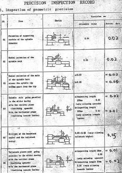
Minilathes are inspected prior to leaving the factory and some vendors include an inspection report with the lathe. This sample report shows the standards this vendor required be met; the procedure given below can improve accuracy considerably ("Radial pulsation" is also known as runout; error values in the report are in mm). Note that Item 5 in the report requires the tailstock be higher than the headstock by 0.03mm to 0.08mm(about 1 to 3 thou).
Some machinists turn a test bar to align their lathe using the "Two Collars Test". As noted via links in this section, the TCT works but doesn't easily allow multiple readings (per a test bar or RDM) to produce a plot characterizing the lathe bed.
I used Rollie's Dad's Method (this RDM concept paper is also found in the 7x12 Group's files) of aligning a lathe's spindle axis to the ways but stacked the deck to simplify its application. Study and compare the original RDM concept document to the less general execution scheme outlined below to understand how and why the "simplification" works.
At right is my setup: a piece of 1/2" drill rod extending 10.5" from the chuck, the compound removed and a DTI mounted in its place (a toolpost mounted indicator works nicely too). In order to achieve 10" between the left and right measurement points (not really necessary) I removed the threading dial. The bar holding the DTI is set parallel to the test rod and oriented so that the DTI finger can be easily adjusted in height without changing the horizontal position. The horizontal position of the DTI is adjusted via the cross slide.
NOTE: The 1/2" x 10" steel test bar is not rigid -- it bends slightly under its own weight. The error due to sag of a 1/2" test bar is small so if your goal is simply to eliminate taper due to a headstock/bed alignment error you can safely ignore this error. I calculate that my test bar sags about 7/10 at the far end. This won't affect horizontal measurements noticeably but it will affect vertical measurements, i.e. the headstock will appear to tilt down by about this amount in addition to any actual tilt. This error from sag can be reduced by using a larger diameter test rod and/or a hollow test rod (pipe). I used the formula for a uniformly loaded cantilever beam found here to calculate sag. The indicator force against the rod, about an ounce, adds an additional 2/10.
To stack the deck: 1) Use an accurately round test rod (drill rod, a shaft from a shock absorber, or a shaft from a line printer are good but can be improved) to eliminate variation in rod diameter from the RDM equation, 2) Use a straight test rod and adjust chucking so the far end has minimal runout (the DTI is already set up) - preferably under a thou runout to minimize cosine errors, and 3) Adjust the DTI at the chuck end to deflect equally above and below zero (making this average zero) to eliminate this term from the RDM equation.
After taking a reading on the far end of the test bar, always return to the chuck end and verify that it still averages to zero. This is a cross check to ensure that nothing got bumped while making the reading.
If this is your first trial of RDM it may be helpful to print John Wasser's RDM page plus copy the simplified version above into WordPad and print it for reference.
Once you muddle through the above, it becomes clear that with your trusty test rod and DTI you can measure a lathe's vertical or horizontal axis error in under a minute -- something I puzzled over for a long time without getting anywhere prior to discovering the RDM article. If you don't have an accurately ground test bar and a DTI you can still make the RDM measurement by working from the original article, it just takes a few minutes longer.
Using the above approach I made measurements along the top and front of the test rod. The spindle was slightly off line, where the averaged rod position 10" from the chuck was 1.3 thou closer to the operator and 0.4 thou higher -- excellent for this inexpensive machine but clearly not in the Hardinge category. I heard from a site visitor whose errors were over 10 times as large as mine so not all mini-lathes have good accuracy out of the box.
After determining my spindle alignment error, I removed parts as needed until the headstock was off; the shafts and shift fork were lubricated but the gears were not -- my opinion is that plastic gears don't need lube. It took over an hour of trial and error work using aluminum foil as shims to improve the alignment; the headstock was removed and installed at least 6 times while selecting the best shim arrangement. The spindle now measures 0.3 thou high and 0.2 thou forward at the end of the rod 10" away from the chuck -- as good as I could do because the tightening torque on the headstock retention bolts causes changes larger than the observed errors plus there is some "noise" in the DTI reading from the test rod's surface finish. Shimming is an iterative process where RDM results guide thickness of shims and where to place them. You start out with a guess, evaluate the effect and take another guess, etc. Error decreases as you converge on the correct shim setup but what I found is that it gets shaky when you need to adjust by tenths. Eventually I settled for the values above -- others may have more skill and/or more patience.
To verify that the corrections I made improved things I trued a 1" OD steel round about 3" long by making very light cuts. The taper measured over this length was about a tenth, i.e. at the limit of my measuring ability.
A recurring misconception about RDM is that the accuracy of the chuck or the way the rod is held by the chuck (angle/offset) affects the result. In fact, RDM removes these errors by averaging them out as part of the calculation. The simplifications in the application of RDM suggested above may make it hard to see how this happens; refer to John Wasser's original document to gain a clearer understanding of this elegant technique. The original document suggests shimming the feet of the lathe to correct alignment -- this won't work for the 7x12 because it sits on rubber feet and isn't bolted to a stable surface so you must shim the headstock instead. RDM does assume that the prism/bed which guides the carriage along the ways is absolutely straight... with additional effort you can, and should, verify this.
Note that the original RDM assumed the headstock was accurately aligned with the ways and measured error was due to bed twist, correctable by shimming the feet. Here I assume the bed is not twisted and the error is due to misalignment of the headstock. More than one 7x machine has a twisted bed so anything is possible; it isn't difficult to check for twist before attempting alignment.
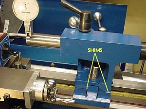
Inspect the contact area between headstock and bed, removing any burrs or defects which might prevent good contact. Chamfer the holes for the headstock bolts slightly where they mate to the bed and also the holes in the bed where they mate to the headstock; burrs here can affect the alignment.
I found the mating part of the headstock was deliberately (albeit crudely) ground so the part which fits over the prism makes contact at areas near the left and right ends of the headstock, plus there is a third contact point on the rear flat part of the ways. There is a bolt near each of these contact points. This clever design makes it reasonably straight forward to adjust.
Apply machinist blue or Sharpie pen ink to the headstock where it mates to the prism. Carefully place the headstock in position and slide it back and forth on the prism about 1/8", then remove it. The blue on the prism and the clean points in the headstock V will indicate the contact points. Verify that the contact points are near the bolt holes, preferably toward the ends of the headstock from the respective bolt holes.
The shims to shift the horizontal or vertical alignment should be placed at the indicated points. To adjust the horizontal alignment, apply a shim to one 45 part of the prism near one hole and to the opposite 45 on the other hole (I extended each shim down the side of the prism to the horizontal part of the bed and held it in place with a dab of grease). I used folded aluminum foil for a shim so it may have compressed a bit; I used one 3 thou and the other 2 thou to shift my horizontal alignment by 0.0011 at 10" -- this may help in estimating the shims needed.
To adjust the vertical alignment, apply a shim to both sides of the 45 on either the chuck side contact point (to angle the chuck upwards) or apply a shim to both sides of the gear side contact point (to angle the chuck downwards).
As the 3 headstock bolts are tightened, torque can be used to "fine tune" the last half thousandth or so measured 10" from the chuck.
I used a 22 inch long piece of 1/2" drill rod I had on hand, passing it through the chuck until 10.5" protruded, then tightening the chuck. In retrospect, this was a poor way to proceed because the rod picked up some small scratches in the process of passing it through the chuck; these scratches affect the DTI reading by causing jumps of up to 1/2 thou as the rod rotates. I should have cut off a foot of drill rod, dedicated it to RDM, not passed it through the chuck, and preserved it in a velvet lined box when not in use. Rollie's dad owns a car repair shop and uses old shock absorber rods -- better than drill rod because they're hardened and tough to scratch (and they're free!). Enco has hardened and ground rod but keeps it hidden as 505-3290 -- this rod is VERY scratch resistant but more expensive than drill rod.
Prior to aligning the tailstock, check the tailstock "V" for "ridges" since these can affect repeatability of tailstock error measurements as well as tailstock alignment. Verify contact between the tailstock base and the lathe bed, adapting the ink approach outlined for the headstock in Practical Details above. Also see my tailstock notes for more on the difficulties involved in precise tailstock alignment.
 The tailstock's angular alignment to the ways should be corrected prior to adjusting tailstock height and therefore prior to adjusting the headstock. Improving the angular alignment is quick but getting it near perfect takes time and fiddling because the results of shimming aren't completely repeatable, probably because things seat differently each time. To evaluate the angular alignment of the tailstock, extend the ram and lock it (to take up any slack). Mount the DTI on the carriage and indicate along the top of the ram to measure vertical alignment. Indicate along the front of the ram to measure horizontal alignment. My tailstock's angular alignment seemed fine initially but eventually I found the ram was pointing up and toward the front by 2 thou per 2 inches in each direction. Shims were installed as shown, a 3 thou shim across the rear of the tailstock to base joint and a 5 thou shim (about 1/2" long) on the front, forward of the center ridge in the base (I left the ends exposed for the picture). Shimming the tailstock is much easier than shimming the headstock: remove the tailstock from the lathe, loosen the bottom socket head screw and the rear screw a couple turns -- the base and top will separate enough so shims can be slid in. Re-tighten the rear screw and tap the base a couple times with a rubber mallet to ensure things are solidly seated, tighten the offset adjustment bar if fitted, tap again, tighten the socket head in the bottom, tap again. Install, check, and repeat as needed.
Once the angular alignment of the tailstock is correct then the angular alignment of the spindle should be completed prior to aligning the tailstock to the spindle horizontally and vertically as described below.
Mini-lathes are deliberately manufactured with the tailstock slightly higher than the headstock (see item 5 in this inspection report) to facilitate subsequent alignment. The implication of this didn't register with me initially so I thought I would need a mill to lower my tailstock by 2.5 thousandths. I reassembled my lathe after aligning the spindle and continued to ponder how to align the tailstock height.
Finally, the light came on: raising the headstock is equivalent to lowering the tailstock since the goal is to set them equal. I had to loosen the headstock again (not optimum) to correct the tailstock height error. Shimming the headstock is faster and easier than lapping the tailstock to match the headstock height; future wear may lower the tailstock which can be compensated by exchanging this shim for a thinner shim. My tailstock measured 0.0025 high so I added a 5 thou shim on the rear headstock support point (without disturbing the shims previously installed on the V), raising the chuck (in the center of the headstock) by half the thickness of this shim. This worked as anticipated: the height of the tailstock is now about 0.3 thou high while spindle angular alignment was unaffected. (Paper shims work but are not the best because they can be difficult to remove if re-shimming is needed later, best to use real shim stock or even pieces trimmed from a soda can.)
 Tailstock offset was measured initially by holding the mounting stud of the DTI in the chuck, then indicating on a dead center in the tailstock (easier and more accurate than indicating the inside of the tailstock taper). This quick and easy approach works for horizontal offset but vertical offset can't be measured accurately because the indicator weight affects the reading -- (see below for a better way to make both horizontal and vertical readings with a shop made test bar). Verify the horizontal alignment of the tailstock by taking readings at 9 o'clock and 3 o'clock. Any error here can be corrected using the adjustments provided. It can be tricky to adjust the tailstock because you must rely on the upper screw (under the crank) to hold the horizontal adjustment while you remove the tailstock to access the locking screw underneath. Then, the adjustment may shift slightly as you tighten the lock screw so it often takes a bit of trial and error -- I eventually added a bar and use shims to simplify accurately centering the tailstock horizontally. Theoretically the angular shims shouldn't interact with the horizontal shims -- but they do so if you change any tailstock shim check both angular and offset errors. This interaction may be due to seating errors since it doesn't seem completely repeatable or predictable -- I have about 0.0001 error per inch in residual angular error because this unpredictability prevents getting all settings to zero simultaneously.
A shop made test bar and a variation on RDM can be used to evaluate tailstock alignment. If you suspect your tailstock is out of alignment but want to make a test bar it may be helpful to use the quick method above to ensure reasonably accurate alignment while center drilling the test bar. Also, the ends of the test bar should run absolutely true while center drilling so use a 4 jaw (with protection to avoid marring the test bar) or Bump-Tru. I used a short piece (5+ inches long) of ground rod from a line printer and center drilled both ends. It's helpful to do this carefully so the rod turns as true as possible when placed on the centers (even though RDM can be used to remove any residual error).
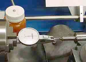
Once you have the test rod, chuck a short piece of scrap rod and turn a 60 degree point on it;  this should run true as long as it is not removed from the chuck but it's truth can be verified as part of the setup. Place a dead center in the tailstock and hold the test rod between these centers, using oil on both centers. With the tailstock locked to the bed, advance the ram so the test bar is gripped firmly but can be rotated with your fingers; tighten the ram lock to minimize movement of the ram in its bore if this is an issue. Set up the mag base with DTI to measure either the top or front of the test bar, see picture at left (click to enlarge).
Move the DTI so it measures about 1/8" from the chuck end of the test bar. Hold the test bar with your fingers at the tailstock end so it can't rotate while rotating the chuck by hand; the DTI needle should not move as the chuck is rotated, proving that the center in the chuck is running true. Set the DTI to zero and rotate the test bar with your fingers, noting the min and max reading. Rotate the bar until the DTI reads mid way between the min and max, then zero the DTI again. (Its easy to zero the DTI for horizontal readings using the cross slide - zeroing for vertical readings can be more of a challenge, depending on your DTI setup. Conversely, for vertical readings it's easy to get the DTI centered on the bar using the cross slide while watching the needle but for horizontal readings I center by matching the DTI finger to the dead center height.) Crank the saddle down the bed so the DTI reads 1/8" from the tailstock end. Rotate the test bar (gripping near the chuck this time) and note the min and max readings. Add the min and max together and divide by 2 to get the tailstock offset, either horizontal or vertical depending on DTI placement. Wind the DTI back to the chuck end and verify that the DTI reads zero as it did initially - if it doesn't, you bumped something and need to repeat the reading. (Note that if you are fussy while drilling the test bar's centers the min and max will be very nearly identical so RDM shouldn't have much effect - and if you're really good then min and max will be identical and RDM won't be needed. My test bar has about 3/10 runout on one end and 5/10 on the other so I need more practice... and RDM.)
It is best to also verify the dead center is accurate. To do this, read the horizontal or vertical offset as described above. Then remove the dead center from the tailstock, rotate it 90 degrees, and take another set of readings. If they repeat the first reading then rotate the dead center another 90 degrees, etc. for 4 total readings. In general, centers are accurate so the readings will repeat. If they don't then be alert for an error in the dead center but also for other error sources like swarf in the ram socket, dings to the dead center or the ram socket, failure to repeat when locking the tailstock to the bed, etc.
My tailstock exhibited repeatability errors, e.g. the horizontal error would vary by up to 2 thou each time the camlock was released, the tailstock moved away and then back and the camlock re-locked. This bedeviled me for a long while before, while working on the carriage gibs, I found (and removed) a small ridge in the tailstock "V".
Prior to alignment my lathe did not drill well from the tailstock -- the center drill would scribe a small circle when brought slowly into contact with work in the chuck, with increased pressure drilling would start but the drill would wobble; there was also a "scrapey" feel when drilling deep holes. Following alignment the drill starts nicely without wobble and is noticeably smoother in deep holes.
The tailstock is more difficult to align than the headstock (although access for shimming is easier). Measuring the headstock error and compensating for errors arising from chucking are handled nicely by RDM, assuming a good quality test bar. There are more sources of error/variability when aligning and/or using the tailstock including: clamping the tailstock to the ways, ram/taper concentricity, and chucking variability.
The method I used for tailstock angular alignment is flawed in that it assumes the exterior of the ram is accurately concentric with the interior taper. This alignment in my tailstock has an error of 1.5 thou per inch = .086 degree (which seems pretty precise when stated in degrees). I made a lever drilling attachment and while evaluating its accuracy ran into the error in the tailstock's taper alignment (made obvious by the increased distance from the taper to the end of the drill bit). Oddly, removing the rear shim inserted while aligning the ram to the ways aligned the taper correctly; hard to believe this was done deliberately during manufacture, but maybe.
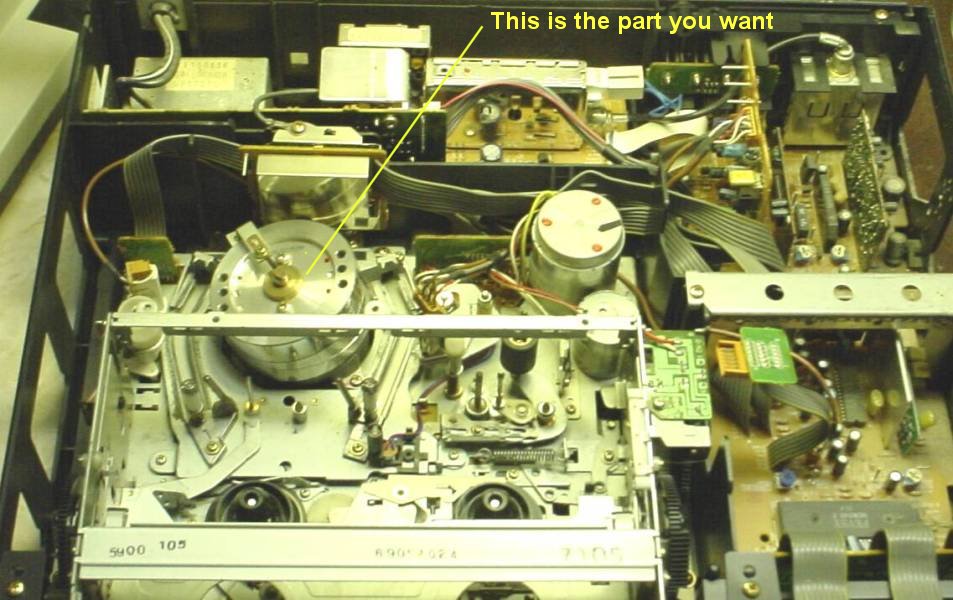
It is instructive to check the tailstock chuck, indicating on a hardened and ground pin held in this chuck. This checks the overall error in the tailstock plus the arbor and the chuck itself -- my HF chuck isn't a precision gripping device although the basic alignment of chuck and arbor is good. Each time the hardened pin is gripped in this tailstock chuck the offset changes by up to 3 thou although the angular error isn't affected. My Jacobs Superchuck has less variation in offset, typically being under 1 thou. (An inexpensive source for a suitable hardened pin is the shaft from a discarded VCR's head motor.)
If the goal is to improve drilling performance from the tailstock then aligning the tailstock based on measurements on the ram leaves ram/taper concentricity and chuck idiosyncrasies uncompensated. Using a hardened pin held in the chuck for alignment works but variability in how the pin is gripped by the chuck can add considerable error and is difficult to determine. Setting horizontal and vertical offset by measuring on the face of a dead center seems to be reasonably repeatable. One scheme would be to make h/v offset measurements with the ram retracted and extended, then take the difference to find the angular errors -- I haven't tried this (yet) but it suffers from being more complicated to explain and taking longer to make the measurements.
Reducing tailstock error is quick and easy and the improvement in operation is easily seen. Diminishing returns set in when attempting to achieve errors below a thou or so. The DTI is a double edged sword allowing measuring and correcting alignment errors but also showing residual and repeatability errors remaining after one's best effort. Perhaps it is best to be happy with the low hanging fruit :-)
"Carefully adjust the vertical position of the DTI for maximum deflection (center of the test rod's side)" seems easy enough to do -- and it is easy if you use a DTI mounted on a QCTP because then the tool height adjustment moves the DTI vertically. With the DTI on a mag base, ensuring the DTI moves vertically is more difficult -- the plane of movement is usually inclined slightly. Getting the DTI vertical position accurately on the center of the test bar based on needle deflection assumes the DTI moves vertically. Make this movement as near vertical as possible to minimize small errors that are difficult to analyze and quantify.
To check whether the cross slide is perpendicular to the ways, mount an indicator on the CS either on the toolpost or using a magnetic base. Remove the chuck jaws and touch the face of the chuck near the periphery of the chuck face and at center height, i.e. on the near side of the chuck and set the indicator to zero. Lock the carriage so it won't move inadvertently as you move the CS. Mark the point touched with a Sharpie, then rotate the chuck so the marked point is on the far side and at the same height(you'll have to help the indicator finger across the chuck slots). Advance the CS until the indicator again touches the marked spot on the chuck. Any difference in reading indicates (pun) that CS travel is not perpendicular to the spindle axis. If the CS moves toward the headstock slightly as it is advanced then a faced surface will be slightly concave; if the CS moves away from the headstock as it is advanced then a faced surface will be convex. Generally a very slight concavity is desirable, perhaps a tenth or two per inch. In practice, this measurement is helpful but not completely reliable: often tool pressure increases as the tool approaches the center while facing (because sfpm drops) and this tends to make the result convex, depending on the work material, RPM, slide loosness, tool sharpness, depth of cut, etc. Bottom line: if it's close it's probably OK.
Correcting the CS travel to make it perpendicular requires modifying the CS dovetail (or the saddle "V" way) slightly which is beyond the scope of this document.
Generally, the prism and bed of 7x machines is straight but occasionally a machine produces puzzling results when applying RDM. The concept behind RDM is to compensate various errors in measurement (bent test rod, chucking angle, etc.) mathematically by subtracting them out. This allows measuring the distance between the prism and the (theoretical) center of spindle rotation. If the bed is twisted or the prism curves then the result will be in error and attempting to reduce the measured errors by shimming may produce unexpected results.
Checking a 7x12 for bed twist requires a surface plate or other flat surface (mill table); remove the lathe's rubber feet, place it on the flat surface and verify all feet make contact with no rocking, where rocking likely indicates the bed is twisted. Vertical curvature of the bed can be detected with a straight edge. Assuming all is OK, verify the bed/prism straightness by taking additional RDM readings as suggested below (where I assume you're using the simplified RDM described earlier). On larger lathes where it is impractical to place the lathe on a surface plate use a sensitive machinist level to verify the bed isn't twisted. Correcting for bed twist or wear is beyond the scope of this document.
The (theoretical) center of spindle rotation is a straight line so if the bed/prism is not straight then the distance between the prism and the center of rotation will vary non-linearly - this sounds complicated but is straight forward to detect. To do this, record RDM type measurements at evenly spaced intervals along the test rod. For example, record a RDM type reading every 2 inches on a 10" long rod, i.e. 6 readings. Each RDM reading is the (min+max)/2 = distance change between prism and center of spindle rotation. Because these readings are taken at equal intervals, the change between adjacent readings should be equal. That is, the reading nearest the chuck is zero (set that way using the simplified method), so if the reading 2 inches from the chuck is 1/2 thou then 2 inches farther from the chuck it should be 1 thou, and readings should increase 1/2 thou for each additional 2 inches moved toward the tailstock. If the values change by differing amounts then the bed is twisted or worn or the prism is curved - use common sense in interpreting the variation found(changes of a tenth or two are likely measurement errors/noise). Correcting defects in the bed or prism is beyond the scope of this document.
To better understand the results of a "soft foot" (no support under a tailstock foot) I made the above described RDM type measurements (horizontal only) on my lathe with it supported on all 4 feet and then with a pad under each of the tailstock feet so it was supported on 3 feet. In addition, I used a sensitive Starrett level to detect bed twist. I used RDM to adjust my 7x12 in 2004 which improved its accuracy considerably - but it has apparently changed since, according to these 2014 RDM measurements.
Some mods to my 7x affected the measurements procedure. I added an extension bar to the feet to improve stability; the rear foot is farther from the lathe center line than the front foot so the applied twist differs when a pad is added under one of them - more twist when the rear foot has the pad.
The dog clutch trigger mechanism limits the carriage travel toward the tailstock slightly so 2014 RDM measurements spanned 9" rather than 10" as in 2004. My ER-32 collet chuck held a 3/4" case hardened ground bar (by Thomson) for these RDM measurements. The Thomson bar is hardened but I used the collet to ensure it didn't get scratched - alternatively, thin sheet aluminum would protect it from the 3 jaw.
 Measurements were made with all 4 feet supported, then with a 1/8" steel pad under the rear tailstock foot, then with this pad under the front tailstock foot, then measured with all 4 feet supported again as a consistency check. The data was entered into a spreadsheet which did the simplified RDM calculation and charted the results (at right, click to enlarge).
The curvature in RDM results was a surprise - although I describe this check above, I hadn't run it on my 7x12 because in 2004 I hadn't considered how to detect bed defects; work turned after using RDM to improve alignment seemed fine. That was over 10 years ago, however, and things apparently changed over time. Oddly, the first 5-6 inches of the bed still look good via RDM - that's where most of my turning is done, so I didn't notice the change. The RDM readings are non-linear (curved) so part of the error is from a bed defect - since I didn't run this test in 2004 I don't know whether this was a manufacturing defect or stress relief occurred in the bed casting with age. The "Bow" calculation in the spreadsheet shows that an unsupported tailstock foot has negligible effect on this bed defect.
An interesting observation: per the chart, twisting the bed slightly (by padding a foot) moves the curve but has little effect on the shape of the curve since it is caused by a warp in the bed.
As part of this experiment I used a Starrett machinist level to detect bed twist caused by supporting only one of the tailstock feet. The compound was removed and the level placed on the cross slide oriented parallel to CS travel. Moving the carriage along the bed causes the level to show bed twist. The bubble movement is small when the lathe is on all 4 feet but there is a small movement showing the bed tilts rearward in the middle, looks like about 2 thou, more or less. Movement was judged by inserting a shim of the stated thickness under one end of the level to restore the bubble to its original position. When the pad is under the rear foot there is a twist of about 5 thou +/- induced. I added an ink mark on the vial adjacent to the end of the bubble - this made it easier to judge movement by watching the gap between the ink and the bubble. Parallax is an issue so adding a "sight" (just a piece of wire held by a magnet) helped to ensure the little gap was viewed from the same angle at all carriage positions. I expect these readings could be up to 5 tenths off -- I found it more difficult to judge bubble position than read the DTI.
The sensitive level and RDM agree that the bed on my 7x12 is not straight. Further, the level shows that both ends of this bed are in the same plane, where RDM does not provide this information. I'm not aware of a simple way to correct this - the bed needs to be re-ground or scraped true, neither of which is economically feasible for this grade of lathe. RDM provides a profile of the curvature calibrated in thou so in some cases it would be possible to minimize the apparent error by moving the curve so its average distance from zero is minimum over the part of the bed that is most used (by chance, my lathe happened to work out close to this).
A commercial test bar is typically a precisely ground hardened steel bar with an MT taper on one end; diameter is constant along the length, the bar is straight and runout at the far end is less than 4/10. Cost varies from $60 to $300 depending on size and quality.
A modest cost substitute for RDM measurements is case hardened linear shafting by Thomson; a 3/4"x12" shaft is about $12 from Enco. This is specified as round within 80 millionths and straight within 1 thou, more info from Thomson.
Improving spindle/bed alignment is an iterative process where initially the error may be large but reduces as the process proceeds. A piece of drill rod works fine when the error is relatively large but as the error gets smaller noise in the readings due to imperfections in the bar limits the ability to discern the error signal. The bar diameter may be slightly eccentric and the diameter may differ slightly between the measurement points. Plus, surface roughness adds to the difficulty in reading the indicator. It is possible to reduce the effect of all three by lapping a home made test bar.
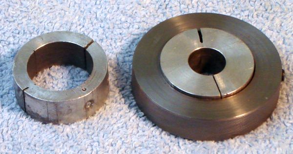 The laps shown are made from 1.25" aluminum bored to size and slit. The lap holder is steel and includes a set screw to adjust the lap size and also to keep it from rotating in the holder. Lapping is a statistical process in which the lap and the work get rounder and in the limit the outcome would be a perfect circle. A little Clover valve lapping compound or dry abrasive+oil works well.
You can feel the eccentricity of items as lapping begins - the lap twists in your hand with each rotation. This eccentricity goes away pretty quickly because much of it initially is tooling marks rather than solid metal. In addition, running the lap axially causes the diameter to become constant over the lapped area, one can feel differences of less than 1/10 so it's easy to convert a bar that looks round and constant diameter to one that IS, within better limits than I can measure. As a fringe benefit, the surface noise as seen by the indicator is greatly reduced. Not generally a long process, it typically takes under 15 minutes if the bar is reasonably constant diameter with a decent finish to start.
Lapping is helpful when you're trying to get every bit of possible resolution from RDM - it improves the signal to noise ratio when the errors being measured are small.
Test bar length is a tradeoff where greater length amplifies the error signal (without adding noise) but results in more sag, so sag compensation plays a bigger part. Larger diameter is a help in reducing sag as is a tubular test rod - reducing weight reduces sag.
In describing how to align a small lathe we'll start by describing the essence of a lathe and then generalize this theoretical model just enough so it covers the practical issues that arise in the alignment process.

In our model the bed of a lathe is a precisely rectangular block with perfectly flat sides(gray in the drawing above). Our theoretical carriage (not shown) can travel along the bed, guided by the front and back edges which function as the ways. This carriage can hold the tool tip a constant, precise distance from the ways. The headstock, red in the above drawing, is fastened solidly to the bed and holds the spindle (green) such that the spindle's axis of rotation, shown as the black line extending from the spindle, is precisely parallel to the ways. Should the spindle's axis of rotation not be parallel to the bed ways then work turned on the lathe will be tapered along its length.
Spindle alignment consists of measuring any deviation from parallel between the spindle's axis of rotation and the lathe ways; the goal of alignment is to reduce this deviation. The first step in moving from the model to the real world is expanding the theoretical spindle axis to something which can be measured with an indicator.
Lathe manufacturer's typically use a test bar for alignment, where this bar is hardened steel, accurately ground to a constant diameter (to 0.0001" or better) of 1" or so over its full length and it is guaranteed straight within a thou or better. Test bars generally have an MT taper on one end; when the taper is placed in the spindle, runout at the far end of the bar is 0.0004" or less for a good quality test bar. That is, the test bar is on the spindle's axis of rotation with a maximum error of 4/10 - so measuring the test bar's change in horizontal (or vertical) position using an indicator mounted on the carriage yields the deviation from parallel between the ways and the spindle axis. The error in this measurement caused by runout can be removed by averaging the high and low readings at any measured point. The center of the test bar, when corrected for runout, is effectively the spindle's axis of rotation. The surface of the test bar is one bar radius from the bar's center so setting the indicator to zero at the spindle end of the test bar causes any change in reading as the carriage moves the indicator along the test bar to read the change in the bar's center; when corrected for runout this change yields the deviation between the spindle's axis of rotation and the bed ways (assuming the indicator is centered on the test bar either vertically or horizontally as appropriate).
There are several practical issues which can cause the spindle axis of rotation not to be parallel to the bed ways for part or all of the bed length. Some common issues are:
Bed twist is commonly diagnosed using a sensitive level placed on the carriage (or cross slide), oriented perpendicular to the spindle axis. The level is shimmed to read level with the carriage at the headstock end. The carriage is then moved to the tailstock end of the bed, where any change in the level's reading is caused by bed twist. This is corrected via the lathe's jack screws etc. or by shimming the lathe's feet. After corrections, in many cases it is helpful to allow things to settle down for a while (a day or more) before verifying level and proceeding to other alignment measurements.
After bed twist is corrected, a bent bed can be diagnosed by taking a series of readings at intervals along the test bar and plotting the deviation from parallel vs position along the bed. If these readings, corrected for runout, plot as a curved line then the bed is likely worn or bent. Correcting for these issues is beyond the scope of this document.
After bed twist is corrected, headstock alignment can be diagnosed by taking a series of readings at intervals along the test bar and plotting the deviation from parallel vs position along the bed. If these readings, corrected for runout, plot as a straight line then the headstock may need to be aligned with the bed. Some lathes include screw adjustments for this but most need to be scraped or shimmed to improve alignment. This document describes shimming a 7x12 lathe to improve headstock alignment - the measurement concepts apply to many lathes but the correction described is specific to the 7x12.
This overview of lathe alignment mentions using a test bar. Lots of interesting tests mentioned. The spec on the test bar is 4/10 maximum runout. This would prevent accurate alignment so they must average it out -- which is RDM (except they don't call it RDM).
The issue with test bars is they are expensive, typically $100 to $300 for a good quality bar; the 7x12 would need MT2 and MT3 test bars to test headstock and tailstock. It didn't seem reasonable to spend that amount to align a $300 lathe.
The concept used to align the tailstock is similar to the above except we assume that bed twist and spindle axis errors have already been minimized. Assume a line connecting the spindle axis of rotation at the headstock to the center of the tailstock ram. Again, we need to expand this theoretical line to something that can be measured, which we do by using a test bar. This test bar differs in that it needs to be perfectly drilled to accept dead centers on each end and, as usual, it needs to be constant diameter (within 0.0001"). To hold this test bar assume perfectly ground dead centers at the spindle and tailstock. Holding this perfect test bar between these perfect dead centers one can simply compare readings (vertical or horizontal) at the headstock and tailstock ends to find the horizontal or vertical tailstock alignment error.
In practice nothing is perfect, but again RDM can be used to minimize the effects of our less than perfect equipment. Rather than repeat the details here, see the description of how I used RDM for tailstock alignment.
About a year after purchasing the 7x12 I started to notice work was often tapered. Researching this, alignment checks were suggested. Once I understood the alignment concept, I realized I needed a test bar. Being a certified cheapskate, I looked for a method that didn't require an expensive test bar and ran across a PDF, written by John Wasser, describing "Rollie's Dad's Method" (RDM). This light-hearted paper explains the elegant RDM concept and identifies most of the problem areas that could cause erroneous readings along with ways of minimizing these error sources mathematically. Clearly it isn't meant as an execution plan -- correcting vertical headstock error by shimming both tailstock legs is an obvious joke ;-) To align my lathe I converted John Wasser's description of RDM to an execution plan, which I consider a simplified version of RDM because it eliminates most of the correction calculations by using an accurately ground bar. RDM removes effects from curvature of the test bar or minor runout of the chuck. Initially I used 1/2" drill rod for a test bar (because I didn't realize the sag was enough to affect the results) but have since purchased a 3/4"x12" case hardened Thomsen linear shaft ($12 at Enco).
As I use RDM, with a constant diameter test bar held in a collet or chuck, RDM mathematically cancels the effect of runout and/or bend in the test bar. By using a DTI and setting it to read equally above and below zero adjacent to the chuck, the near end offset is zero so it isn't needed in the RDM calculations. The calculations required are reduced to adding the hi+lo readings and dividing by 2, yielding the change in spindle axis vs bed way directly at any point along the bed. Because it is quick and simple to take these readings I can plot the error vs bed position nicely using a spreadsheet: see example with several sets of measurements. Given the plot of error vs position one can try various corrections to improve accuracy in the area of the bed where most work is done, possibly sacrificing accuracy in another area of the bed which is seldom used. This bed characterization can be very helpful when visualizing what's going on when a lathe bed is worn or warped.
Minimizing Runout: If you're willing to work at it you can lap a straight 1" round steel bar (preferably a tube), use a 4 jaw and set the runout near the chuck to nil, then set the runout at the far end to 4/10 or less by tapping it in the right direction as you incrementally tighten the jaws. It takes a few minutes to do this but at that point you have the test bar aligned exactly on the spindle axis. This should perform just like a commercial test bar. Of course, you should use RDM to correct for any minor runout remaining, just like when using a real test bar. Or, you could chuck the lapped bar in a 3 jaw, accept a thou or so runout, push the high side on the far end as you tighten the chuck incrementally and get runout to a thou or so, then use RDM - my guess is there will be little difference in results.
From a different perspective, there is a noise floor set by things like indicator resolution, surface noise, bed wear, etc. and this floor limits the ability to discern the spindle/bed deviation because as one iterates toward perfect alignment, deviation is reduced to the same magnitude as the errors comprising the noise floor. The refinements to Wasser's RDM suggested here are simply ways of minimizing some obvious noise sources so the deviation signal is more easily and accurately extracted. Using RDM without these refinements is akin to using a commercial test bar that got a little rusty in storage: one wouldn't expect the best performance.
The minilathe isn't like most American lathes where the headstock is accurately aligned to the ways at the factory so bed twist and wear account for most spindle/bed alignment errors. Minilathes generally have beds that are new and straight but headstocks that aren't aligned to the ways. However, anything is possible (My 7x12's bed has a bend in it, I've seen another 7x12 with bed twist and I've heard of a 3rd machine with a bend) so one should verify that the bed isn't bent or twisted prior to aligning the headstock to the ways.
There is another alternative to an expensive test bar: the "Two Collars Test" (TCT). Description of one variation here: TCT in J. Latta's article. Reading J. Latta's description, turning the outer collar sounds challenging. Some confirmation in a HSM forum post. Of more concern is that the minilathe headstock needs to be removed during alignment and it would be possible to accidentally bump the test bar in this process - this could require re-machining the two collars which in turn would mean reassembling the lathe, extending the time and effort needed considerably. In the TCT measurements are taken on a freshly machined surface introducing some surface noise into the readings - unlike RDM where the test bar can be lapped to minimize noise.
The J-Latta variation of the two collars method works well according to the Wrathall site (site disappeared). ; a 2" micrometer is needed to get full accuracy from this technique. If the test bar is bumped accidentally while installing shims then the test bar may need to be re-trued for which the 7x12 must be reassembled (motor, motor controller, etc.) or you could use RDM (see above)to accommodate any modest eccentricity introduced. J-Latta's underlying measurements are similar to RDM but the test bar is turned down to run true and be identical size at the two measurement points. Some time is required to true the test bar and get the collars to identical diameter, where RDM uses calculations to remove these artifacts from the measured values without machining the test bar. There are variations of the two collar method that work by re-truing both collars without moving the cross slide, then evaluating the difference in diameters with a micrometer; these variations are difficult to use on the 7x12 when adding shims because multiple trials are generally necessary to select the correct shims and the lathe must be reassembled (motor, controller, etc.) to re-true the bar for each trial. Plus the bar must be re-trued when fine tuning the alignment via headstock bolt torque. RDM can be used to evaluate the alignment of a lathe which cannot be powered up, a major advantage in some circumstances.
A drawback of the Two Collars Test is that it provides only two readings, one near the chuck and a second reading at a chosen position along the bed. Unlike a test bar (or RDM), where the lathe bed can be characterized by taking readings at multiple positions along the bed. The TCT works well when the bed is known to be straight and the headstock is aligned with the bed - then the TCT can be used to fine tune the bed twist, as described in this South Bend document see page 16.
If you have a comment on this site or its contents,
click here, scroll down and click again.