* GadgetBuilder.com *
Last Modified:
A rite of passage for mill owners is the tramming process, where the head is adjusted to be (almost) perfectly perpendicular to the table. The Homier mill is no exception; my mill's head was slightly off, typical for all mills. The documentation provided did not cover how to tram the mill -- the column and base looked monolithic except that there were 4 large bolts adjacent to the base.
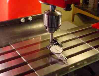
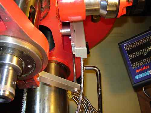
The table was centered to avoid any tilt and the head was set low on the column and locked. A Sharpie was used to mark the fore and aft measurement points on the table(see picture above); the left and right points were judged based on the table slots. To minimize the DTI's movements a piece of glass was placed on the table for the initial work (both the table and the glass must be very clean: even one small piece of swarf could ruin the accuracy of the readings).
A drill chuck was used to hold a rod appropriate for my DTI clamp and the DTI was mounted as shown to allow measuring the variation in distance between the spindle and the table. The accuracy of the chuck and the straightness of the rod do not affect the readings; using a collet to hold the rod will not allow more accurate readings. As with RDM for lathe alignment, taking the difference between readings eliminates errors due to these sources.
Four readings were taken in order to judge the alignment error initially, the "Before" readings in the table (in thousandths). The diameter of the circle touched by the DTI's probe was 8 inches. The readings before and after tramming are shown in the table below:
| Homier MillDrill Tram Readings | |||||||||
|---|---|---|---|---|---|---|---|---|---|
| Front | Rear | Left | Right | ||||||
| Before | 0 | +1.0 | 0 | +7.5 | |||||
| After | 0 | +0.1 | 0 | +0.1 | |||||
The four bolts surrounding the column were loosened and downward pressure was applied on the front of the head. This caused the column to rock forward slightly and cracks opened between the column and base: as anticipated, it was not monolithic. 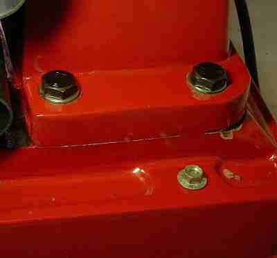 The castings seem to have been bolted together, sanded and then filled with a soft material before painting. When the junction between the parts opened, small particles of this filler found their way into the joint without me realizing it. I added paper shims in the appropriate places to reduce the error and re-tightened the bolts. The error lessened but further adjustment was needed so I repeated the process. The error changed but not quite as expected. I did this several times before realizing that bits of filler were disturbing the process. I then scraped the joints clear with a thin metal piece (most of the filler was on the rear) and then lightly gripped pieces of paper in the mating joints and pulled them out to remove the filler dust. The external area of the rear joint was scraped and filed to further remove filler as part of the cleanup process. The picture shows where the filler broke away toward the rear of the right side; the edge of the paper shim is visible peeking out of the joint.
Once the filler was cleaned off, tramming was predictable and quick, being completed in about a half hour. I found an easy method of inserting shims which wasn't obvious to me initially. The head/motor is approximately balanced on the column; by pulling down on the front of the head with the retaining bolts loosened, the column tilts forward slightly. The column base has an area forward of the front bolts around which the column base cantilevers upward, raising both sides and the rear of the column off the base -- paper shims can be slipped into place easily on these 3 sides while applying downward pressure on the front of the head with the other hand. On my machine the mating surface between the mill base and the column base does not touch all the way across on the rear so shims work best on the sides of the column base. If shims are needed at the front of the base, replace the plate glass on the table with a block of wood, then use the quill's fine feed to apply downward pressure via the rod which will raise the head, allowing a shim to be slipped into place on the column front.
Once the alignment was approximately correct I completed tramming with the plate glass removed (more care is needed while turning the spindle to the measurement points because of the T slots) to eliminate that as a source of error. The "After" readings in the table were taken with the glass removed.
Update: the tram drifted slightly over 3 years so I recently re-trammed. Paper shims are a pain to remove because it is difficult to get at the area and they must be scraped off when they've been in place for years. Best to use brass or stainless shims to avoid this.
Click to Enlarge
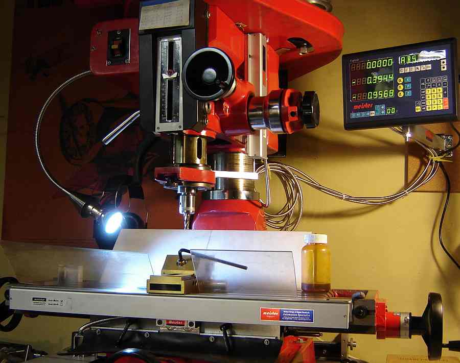
In November 2008 I installed a Meister Top10 3 axis DRO on my Homier mill. Installation took a while but wasn't difficult.
The Z scale was bolted to the head using a spacer near the lower end to align it parallel to the spindle. A square bar was bolted to the spindle clamp and drives the DRO read head via a short round bar. Once installed, the Z readout was immediately helpful in making the X and Y mounts.
The X scale was mounted in place of the movable stops using 1.5" aluminum angle (even with the table top) to protect the top of the scale. A piece of 1/4" aluminum was milled to space the read head and also hold the bar for the way protector. The aluminum shield provided with the scale was modified by removing the mounting
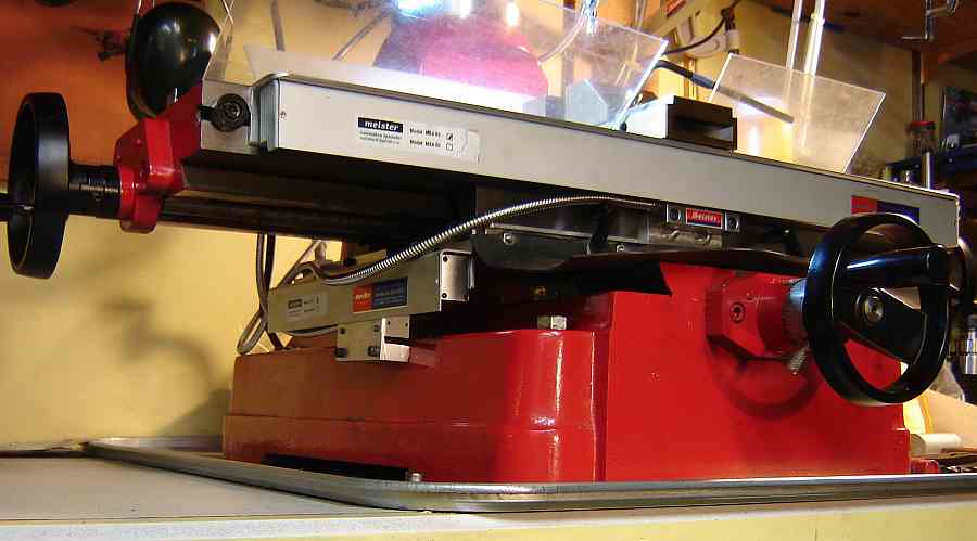 lip so it would fit in the space available - I wanted the security of the angle bracket protecting the scale from accidentally dropped items.
The Y scale is less likely to be damaged by dropped items so a 1/8" aluminum plate was mounted to the carriage and the scale bolted to it using the Meister supplied shield. A spacer, angled 5° to match the mill base, was added to position the bracket that holds the Y read head.
The armored cables which connect the scales to the display are longer than needed so the excess is hung from a hole added to the mill's motor plate; not elegant but it keeps them out of harm's way.
One awkward point to this setup is that the X scale blocks access to the front ball oiler. The front ways can be oiled by cranking the table to one side, oiling the extended area, crank the table to the other extreme and oil that end. I milled the aluminum angle away over the oiler but it is accessible only with a hypodermic - possible but difficult.
UPDATE: On 27 September 2010 the Z axis input to my DRO failed. The Z readout flashes the minus sign while the Z scale is moving but displays zero. The Z scale works if connected via the Y input. Occasionally the Z scale will work normally for a short time but it is no longer reliable. I use the DRO infrequently so it had perhaps 40 hours of ON time prior to failure, i.e. it is most likely infant mortality. Warranty was 1 year (expired, of course), quoted repair cost is $155 including shipping from Singapore. I don't often require Z readout so I haven't had it repaired...
UPDATE: 2 November 2024 - John Barron suggested looking for a cold solder joint on the board's Z connector. I found that a 50 ohm surface mount series resistor (next to the Z connector) had lifted on one end when it was originally soldered. I re-heated the lifted end with a fine soldering iron and this fixed the Z readout problem. It only took 14 years....
If you have a comment on this site or its contents,
click here.