* GadgetBuilder.com *
Last Modified:
Click to Enlarge
A dog clutch is helpful for threading, combining an auto-stop and automatic thread pickup - the thread chasing dial is no longer needed. Thread pickup is automatic for both imperial and metric threads. The concept is described in "Screwcutting in the Lathe" by Martin Cleeve, where Cleeve shows a dog clutch he built for his Myford. The auto-stop function can, of course, be used for tasks other than threading that involve auto-feed of the carriage. Cleeve's article in Model Engineer (1977) may be available as a PDF.
The underlying idea is to disconnect the gear train from the spindle, wind the carriage back by reversing the leadscrew (keeping the half-nuts engaged), then reconnect the gears to the spindle with the same relationship they had previously. The dog clutch has a single tooth so pickup maintains the relation between spindle and gear train. Because the saddle position/gear/spindle relationship is maintained it is equivalent to stopping and reversing the lathe to move the saddle back for the next threading pass, i.e. the full reverse threading method commonly used on an imperial machine for metric threading. High end toolroom lathes like the Hardinge HLV include a dog clutch and auto-stop; the user retracts the tool and reverses the carriage back to the start point. Per Cleeve, reversing the leadscrew via the drive gears can be very slow for fine threads so reversing via a hand wheel is used here - this works surprisingly well because there is little friction from the plastic gears. I posted a video of the dog clutch in use on YouTube. Al Budden made a similar dog clutch and has an animation showing how it works on his site.
A drawback to this dog clutch is that it is more complex to build than my earlier auto-stop; the dog clutch plus automatic stop mechanism stretches from headstock to tailstock. A limitation of either design is the auto-stop function only works when carriage travel is toward the headstock (although the dog clutch will sync both left hand and right hand threads). I use Richard's threading banjo rather than the original gear hardware; this dog clutch may not work with the original setup (I haven't tried it to see if there is interference).
The dog clutch need not include the auto-stop mechanism if this is particularly difficult to include. The dog clutch could be operated manually, similar to the way the half nuts are used (but with automatic thread pickup), provided the carriage can be returned without opening the half nuts. Given the simplicity of the dog clutch itself, it is surprising the manufacturers don't use a dog clutch (without the auto-stop) and eliminate the threading dial - it would be about equivalent work and would avoid the issues with metric and imperial leadscrews vs thread sync.
Parts for the dog clutch are mostly from junked line printers, where I extract shafts and various springs for reuse. In addition, I obtained a dead Husqvarna sewing machine for the right angle gears to drive the leadscrew for carriage retraction. Plus, a couple of small pieces of 5/8" round are needed for the dog clutch setup itself. A milling machine is helpful but the minor work needed might also be done with careful filing or by milling in the lathe.
Unlike many of my gadgets, some parts of the dog clutch require careful fitting and adjustment to work properly, mainly the stops for the clutch lever and the trigger. The overall mechanism has a fair number of parts so I've tried to provide more construction detail than usual. Someone was brave enough to build a similar dog clutch based on my design, see Dr Al's CGTK site.
This minilathe dog clutch and automatic stop consists of four sections:
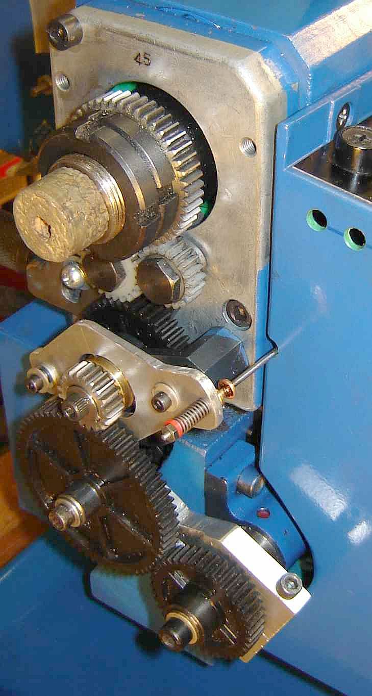
The minilathe's spindle gear has 45 teeth and the tumble reverse gears drive a 45 tooth plastic gear. So maintaining the threading gears' relation to this plastic gear is equivalent to maintaining their relation to the spindle gear.  My dog clutch design replaces the original shaft here with a shaft, idler(holding the output gear) and dog clutch to connect the idler to the driven shaft. The picture at right (click to enlarge) shows most of the trigger/stop mechanism and its connection to the clutch lever; the mechanism is shown with the trigger cocked but the dog clutch not yet engaged.
A lever operates the dog clutch to switch it between connected and disconnected; this lever is driven by the trigger mechanism. The operator cocks the trigger mechanism (which connects the gears to the spindle via the clutch) and the automatic stop pushes the trigger to disconnect the gears at the desired carriage position.
Each of the four sections was built separately since each connects to the next at a single point. I built the clutch and tested it, then built the trigger and verified that it operated the clutch. The stop rod was added and overall operation was verified (by opening the half nuts after the trigger stopped the carriage and winding it back) and finally adding the LS handle and gearbox made the dog clutch usable for threading by returning the carriage without opening the half nuts.
The shaft holding the 45 tooth plastic gear is replaced with a shaft having an "idler", a hollow cylinder with a keyway which holds the outer gear. This idler can spin freely on the shaft. The dog clutch can slide on the inner part of this idler and shares the key that drives the outer gear. When the clutch is moved toward the 45 tooth gear it picks up the dog on the main shaft and drives the outer gear via this key. A spring on the clutch engagement lever presses the clutch against the dog; when the dog aligns with the keyway in the clutch, the clutch moves over the dog - locking the idler to the shaft within one turn of the spindle. While engaged, the clutch ring remains over the junction between the idler and the shaft; when disengaged the clutch ring is on the idler only. Al Budden built a similar dog clutch and included a helpful animation of the dog mechanism's operation.
The shaft which holds the 45 tooth plastic gear has a bearing in the sturdy mount bolted to the headstock. To add room for the dog clutch the mount's shoulder surrounding this shaft was faced off by 0.15".
My CAD ability is minimal so I simply overlaid rectangles to make a side view of the dog clutch mechanism, then used the dimensioning capability to provide the needed information to machine the shaft using the longitudinal DRO on my 7x12(which made it easy to machine).  This drawing omits many key details so use the later version shown below or use the DWG file if your CAD is compatible. The actual parts are shown on this early drawing which should help. There are only 3 main parts (despite the confusion of overlapping rectangles). The original shaft and gear is at lower right.
The idler has a small raised section near the center. Position this so the gear is constrained to the outboard end of the idler, accounting for the chamfer in the gear. The shaft is end drilled and tapped 10-32 so the bolt and washer keep the idler on the shaft. When the clutch is disengaged the shaft spins with the idler stopped; the idler length is adjusted as needed so it can run freely. The idler has a 1/8" keyway for most of its length. I used a 1/8" slot drill to cut this, stopping just short of each end of the idler; this leaves the end of the keyway rounded - the key is rounded slightly on the ends to fit. This ensures the key can't migrate out on either end. The outer end of the 1/8" key must be narrowed slightly at the top so it will fit the metric keyway in the gear.
A 0.040 deep groove is cut in the outer diameter of the clutch using a 1/16" parting blade; 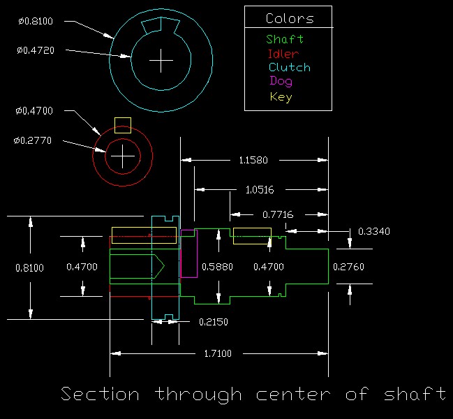 . The clutch slides on the idler and has a keyway so it rotates with the idler. My clutch is from brass but steel should also work well although it needs more effort to file the keyway. I made the keyway in the clutch by mounting the completed turning flat in the mill vise and, using the 1/8" slot drill, making a 1/16" deep semicircular slot, then squaring it later with a file (this keyway needs to be slightly loose so the clutch slides freely). In addition I widened this slot on the side toward the dog by 1/8" to a depth of 0.10" to ease engagement since the dog is the same width as the keyway. I'm a hacker at CAD so use common sense in interpreting the drawing(e.g. I don't know how to display 3 digits rather than 4 so ignore the 4th digit). The DWG file was made with Intellicad V3.1 Free so it may be compatible with other CAD programs.
The inside end of the shaft needs a keyway too, same approach as above using the 1/8" slot drill and thinning the upper part of the 1/8" key to fit the metric 45 tooth plastic gear. A groove and a "C" clip secure the gear, similar to the original shaft.
The dog is inserted in the shaft using the 1/8" slot drill to start a hole which overlaps into the thickest section of the shaft by about 30 thou, see the drawing. Once down to the smaller shaft diameter a twist drill was used and the hole reamed to 1/8".  Depth is arbitrary but should be at least to the center of the shaft. Fit a 1/8" pin made from drill rod such that it is slightly below the largest diameter of the shaft, harden it and secure with Loctite. The dog and the nick in the larger diameter are visible in this picture.
The bearing mount bolts are replaced by spacers turned to 0.338 with spigots threaded 10-32 on the inner end. The rear spacer is flush with the mount and a 1/16" rubber washer is fitted under the lever to space it away from the mount and provide a soft pivot point. The 0.190 outer spigot is D/T 6-32 and a spring is fitted over the spigot to hold the lever against the rubber washer while allowing it to pivot. The front spacer has a shoulder that functions as a stop for the clutch lever. The height of the stop is adjusted so the lever moves the clutch over the dog and up close to the shaft shoulder without touching. This is important so the pins that move the clutch don't rub on the clutch while threading; the pins should only rub while the clutch is changing modes. The 0.190" spigot on this end is also tapped 6-32; the length is adjusted so the lever holds the clutch near but not touching the outer gear. Here, the gear isn't moving so the clutch wouldn't wear but the pins aren't strong enough to absorb the force when the trigger releases so the screw and washer handles this. The spacers are installed by gripping the spigot with a chuck.
The shift lever is 1/8" aluminum, 1.75x3.625". A center line is scribed lengthways and the first hole is 0.3" from one end; the next 2 holes are spaced 1.22" apart. Scribe the line for the center hole for the complete width since it is used to place the clutch pins. Verify that the holes align with the shaft mount and drill them to pass the spigots. Enlarge the central hole to 0.90" and elongate it to 1.08" or so toward the front of the machine; this allows removing the clutch from the lever after installing the pins. Use the scribed center line to drill the holes for the pins; I used 0.047 music wire for pins. Fit the lever onto the supporting spigots with the clutch in place and elongate the front hole so the lever can move the clutch through the required range. Cut the pins to length and, with the clutch in place on the shaft, install the pins such that they clear the bottom of the groove slightly using Loctite to secure them. When this sets up, grind the ends of the pins flush, taking care not to over heat the Loctite. Remove the excess aluminum, leaving enough to ensure the lever isn't weakened. Adjust the spacers which hold the gear mount as described earlier so they work as stops to protect the pins. At this point the clutch is operational and can be tested by controlling the lever by hand. NOTE: When there is no load on the output gear the clutch won't work properly because the gear can be driven by friction rather than the dog - it's confusing the first time it happens...
The Rube Goldberg look of the trigger mechanism is unfortunate but this was the simplest thing that came to mind... and it works. Feel free to improve it, I'm sure it can easily be done. Sizes aren't critical so if you copy this scheme adjust as needed for the material available.
The connecting rods are 0.080" steel wire, bent as needed. A spring on the end of the upper rod compresses when the trigger is cocked; when the dog rotates into position this spring then causes the clutch to engage. 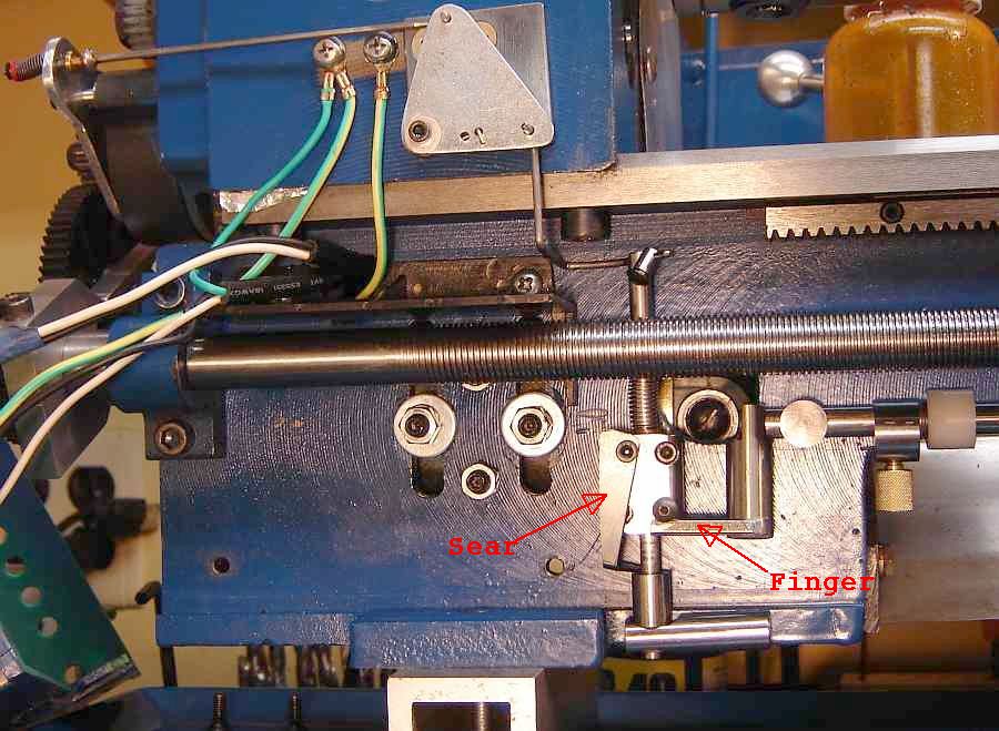 Cleeve's book shows a strong spring but this little spring (from a dead line printer) works well. I threaded the end of the rod 2-56 (the wire is a bit under size but the nut holds) and used a small red shoulder washer to keep the spring near centered. The brass piece is positioned so it allows the lever to rest against the stop when the trigger is cocked; the lever should rest against the other stop after the trigger fires. Solder the brass piece to the connecting rod once it is positioned properly.
The triangular bellcrank is mounted on a small square of 1/8" steel. Ground wires were doubled up on the left screw so two of the bolt holes in the headstock could be used to mount this square using 10-32 flathead screws. There is a "torsional" spring under the bellcrank on the mounting bolt; this has arms that hook into the mounting plate and the bellcrank to force the bellcrank counterclockwise. This CCW force helps disengage the dog clutch after triggering.
 The down wire from the bellcrank is a peculiar shape in order to connect to the trigger rod while avoiding the headstock bolt and requiring minimal material removal from the plastic front cover. I used a piece of soft copper wire to work out the necessary shape, then bent the 0.080 mild steel wire to match. While the steel wire is strong, it does flex slightly in use so I added a stopper to prevent the wire from pulling through the trigger rod as it is cocked.
The trigger body is a 1" long piece of 3/4" round, center drilled to accept the 0.195" trigger rod. I used round material because it is what I had, square would be easier - I milled flats front and back for mounting (ensuring the trigger rod and spring cleared the LS), then drilled and countersunk mounting holes at upper right and lower left for 6-32 socket head screws (the trick is to avoid hitting the center hole while adding all the screw holes). The trigger rod is 4.125 long, 0.233" (6mm) OD turned down to 0.195 for about 2.4" from the bottom - turn 2" initially, then adjust so it stops when the trigger drops into place and the clutch lever is against the stop.
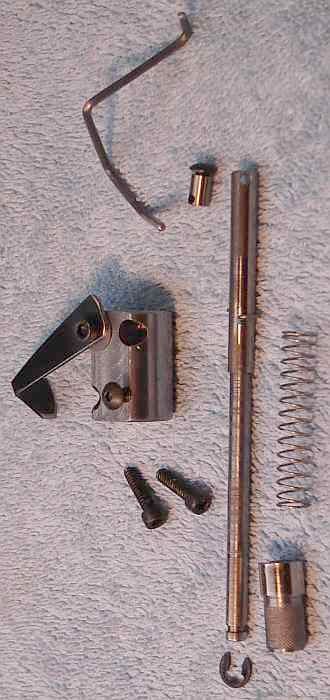
The sear which latches the trigger is 10mm rod with a 0.25 spigot on the end, drilled to pass 0.195". The "L" shape cocking knob is also 10mm rod drilled to accept the spigot on the sear with Loctite to hold them together. An "E" clip on the end of the trigger rod secures things. The trigger is a flat piece of scrap with a right angle bend at the bottom; length isn't critical as long as it clears the bottom of the trigger block and doesn't foul the cocking knob - gravity moves it to the latched position when the trigger rod is pulled down using the cocking knob. The picture shows my first cocking knob which couldn't be worked with the left hand so it was replaced with the "L" shape version. It's a hassle to take it apart (again!) so I kept the old picture.
Once the trigger mechanism is in place and adjusted for length of the turned part on the rod then add a spring above the trigger block to provide positive release of the clutch. In my setup, the bellcrank spring wasn't enough because the force from the wire attached to the trigger rod pulled the rod against the side of the trigger block. This increased friction made operation unreliable until the second spring was added. When triggered, the rod pushes the clutch lever (via the bellcrank) toward the release position but the trigger rod hits the bottom of the bed just before the lever hits the stop so the upper spring then holds the lever against the stop.
A small arm is bolted to the bottom of the apron with two 8-32 screws; it is positioned 1/4" left of the half nut's dovetail. This arm (bent up slightly as necessary)contacts the adjustable stop on the stop rod and slides the rod toward the headstock until the finger on the offset rod pushes the trigger.
My 8mm stop rod is mounted on standoffs made from 12mm line printer rod. These standoffs hold the rod about 0.150" proud of the side of the bed; 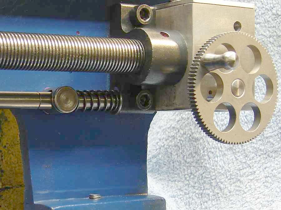 this clears the open half nuts on my machine by over 1/8" but check carefully before drilling holes to mount standoffs. The center of my stop rod is at the height of the bottom bolt on the leadscrew pillow block. The right standoff is 1.25" from the LS pillow block with the stop rod retraction spring to its right along with the E clip; the pillow block is the stop for the retraction spring travel. The stop rod is split near the right standoff (visible in the picture) to allow assembly using a 10-32 spigot on the stub - the left (long) section of the stop rod is d/t 10-32 on both ends. (Without this split the pillow block and gear box would need to be removed to install the stop rod.)
The standoffs have a spigot threaded 10-32 for mounting to the bed; they are cross drilled slightly larger than necessary to make installing the stop rod into the standoffs easy. In making each standoff, face a little off the base as needed to adjust the hole so it is horizontal(should be less than 0.015). To install the stop rod pass it through the left standoff until the stub in the right standoff can be threaded into the longer section. Fit the retraction spring and "E" clip on the right end, then fit the offset rod on the left end. It's a bit of a trick to do everything in the right order.
The stop rod must be long enough so when the right end is against the LS pillow block the left end extends past the left standoff. The stop rod must be short enough so the offset rod which holds the trigger finger doesn't conflict with the trigger mounting block. End drill and tap the stop rod 10-32 once the length is set.
The offset rod which bolts to the end of the stop rod is 12mm. The end which bolts to the stop rod has two parallel flats, drilled to pass the 10-32 bolt and countersunk.  I made this part longer than needed, marked the position for the trigger finger, then added a flat perpendicular to the other flats to mount the finger. The finger is 4.5mm rod with 2 flat sides - odd stuff from an old printer - but a piece of the 1/8" key material would work too. I cut it to length and drilled a hole through the finger and the offset rod to take the 80 thou wire, then riveted them together using a piece of the steel wire as the rivet. The end of the finger was fared into the offset rod on the belt sander. The working end of the trigger finger has a V filed in it to ensure it picks up the trigger nicely. The head of a 6-32 button head screw in the trigger block ensures the finger doesn't stray from the trigger.
The stop rod has a spring and "E" clip fitted at the right end to move the finger off the trigger when the carriage is moved to the right for the next pass.
The adjustable stop is 0.625 steel round an inch long. It is offset in the 4 jaw to turn an eccentric spigot 0.380 diameter (1/2" long), tangent to the OD. The spigot OD is threaded 32 tpi and drilled to pass the stop rod. The thickest part of the 0.625 section is D/T 10-32 and a knurled screw of brass turned to fit. A knurled white plastic nut is made to fit the threaded eccentric where it serves as a micrometer adjustment for stop position.
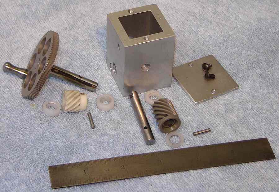
Using the dog clutch for threading requires an easy way of returning the carriage for the next pass while keeping the half nuts engaged.  Positioning a LS crank on the front of the lathe seemed like it would make this easier. I extracted the 1:1 right angle gears from a dead Husquvarna sewing machine and used them in a right angle gearbox as shown. Parts Picture.
The leadscrew was end drilled 0.314" by 1/2" deep and cross drilled 1/4" from the end with a 1/8" drill. A hardened pin was fitted here to couple to the gear box output shaft; the pin is slightly less than the LS journal diameter so it does not touch the bearing surface. The end of the gearbox output shaft was slotted with a 1/8" slitting saw, as seen in the parts picture. The gears are pinned to their respective shafts, with plastic spacers used to position the shafts within the gearbox. The gearbox is held in place by one 10-32 screw plus this connection to the leadscrew (a hole in the front of the gearbox provides access to this screw).
There is little friction or backlash added by the gearbox so this should also work well for fine carriage feed; clockwise rotation of the handle moves the carriage toward the headstock. Initially it took more torque than desired to rewind the carriage which I traced to the half nuts gripping the leadscrew too tightly; adjusting the stop provided on the lower half nut fixed this. I had adjusted this years ago and hadn't checked it since so perhaps it has caused extra drag while threading for some time - the spindle drove it fine, I was the one who complained about the effort....
As with my earlier auto-stop, use caution to avoid a crash - don't trust it until you gain some experience using it since your spring strength and friction in the mechanism may differ from mine. I learned from my earlier auto-stop design so the release springs here are stronger plus the release point is early in the gear train where friction from loading is lower - but I'm gun shy since the crash with the earlier auto-stop. I have deliberately taken much heavier than normal threading cuts and (unlike my first auto-stop) the dog clutch always triggered and stopped the carriage.
UPDATE: I found a new and different way to crash while threading to a shoulder. I've been threading very close to high shoulders and also taking deeper cuts at higher speeds with my new dog clutch. This all came together when a fairly heavy chip rolled up and made its way between the shoulder and the side of the threading tool, stopping the carriage before the finger could hit the trigger. Fortunately, I was running in hi gear with low motor speed/torque so it stalled before anything broke.
When selecting the stop point, allow for the distance the carriage will move to the left as the bit is advanced down the thread flank (and also room for chips...). Failure to do this can cause a crash if the stop point is near a shoulder.
To set the stop point, by experiment I determined the carriage moves 0.335 from the point where the arm touches the stop until it triggers. I made a tool 1" long, 0.335" OD, knurled on one end. Cock the trigger, move the carriage to the desired trigger point, slide the stop up to touch the arm and lock it to the stop rod. Back the carriage away, hold the 0.335" tool against the stop on the rod and bring the carriage back until it just traps the tool between the arm and the stop. Remove the tool, loosen the stop and slide it up against the arm and lock it. Move the carriage to the right, cock the trigger, and slowly move the carriage left until it triggers. Verify the stop position is correct; if needed, adjust the micrometer stop and repeat the test.
In use, as (or after) the stop triggers retract the tool, wind the carriage back via the leadscrew, return the tool to the previous position and put on the next cut, then latch the trigger again.
The clutch is a little disconcerting initially because the carriage doesn't always move immediately when the trigger is latched -- there is often a short delay while the clutch gets lined up with the dog plus there is a definite snap sound as the clutch engages. A minor wrinkle is the handle of the carriage return is moving while the carriage is moving - visible in one's peripheral vision.
After two years of use the dog clutch shows no apparent wear and continues to operate normally. The clutch and other parts on the shaft should be lubricated occasionally. I've found when the clutch is disengaged that the gears are quiet so I forget to put them in neutral - so far having the tumble gears and the first shaft spinning hasn't caused any difficulty. I removed the threading dial.
I've quickly come to trust my dog clutch so I thread at higher speed and also find the threading routine using it simpler to execute, apparently because I don't need to shift my concentration to engage the half nuts at the proper time. Making several "spring" passes after achieving correct depth is very quickly done using the dog clutch and retracting toolholder.
When turning left hand threads I make a run-in (?) groove just to the left of the start point and set the carriage stop so the bit stops at this groove when returning the carriage to the left. The carriage is positioned to the left and the tool advanced into the groove for each pass; the pass is initiated by engaging the dog clutch, which syncs with the thread automatically as usual. Since the carriage is traveling to the right, the auto-stop feature cannot be used so the trigger is tripped by hand after the bit completes the thread and exits on the right side; timing isn't critical since this is in the open. Retract the tool and wind the carriage back to the stop, etc.
This page was last modified
. If you have a comment on this site or its contents,
click here scroll down and click again.